
075582814553

When you look at a 2073 transistor in the TO-220 package, you will see three pins. Here is the exact order for the 2073 transistor pinout:
| Pin Number | Pin Function |
|---|---|
| 1 | Base (B) |
| 2 | Collector (C) |
| 3 | Emitter (E) |
You can use this same pinout for the c2073 transistor pinout. The 2073, c2073, and 2sc2073 transistor all share this layout. If you check the 2sc2073 transistor at home, you only need a simple multimeter. Correct pinout identification keeps your circuit safe and working. Many beginners run into problems because of pinout mistakes, not because the transistor is faulty.
Most circuit issues come from misidentifying the pins, so double-checking the 2073 transistor pinout will help you avoid common problems.
This process is easy for anyone to learn, even if you are new to electronics.
You need to know the exact 2073 transistor pinout before you start testing or using it in a circuit. The 2073, c2073, and 2sc2073 transistors all share the same pinout configuration. These are NPN power transistors, and you will find them in the TO-220 package. When you hold the transistor with the flat side facing you and the pins pointing down, you can identify each pin easily.
Here is the official pinout configuration for the 2073, c2073, and 2sc2073 transistor, as shown in their datasheets:
| Pin Number | Function |
|---|---|
| 1 | Base |
| 2 | Collector (connected to mounting base) |
| 3 | Emitter |
This pinout is consistent for all three types. The base (pin 1) controls the transistor. The collector (pin 2) connects to the mounting base, which helps with heat dissipation. The emitter (pin 3) is usually the output terminal. You will see this same pin diagram in most datasheets for these NPN transistors.
Tip: Always double-check the pinout configuration before connecting the transistor to your circuit. Mistakes can damage your components.
The TO-220 package is a common style for power transistors like the 2073, c2073, and 2sc2073. You will recognize it by its rectangular plastic body and metal tab at the top. The three pins stick out from the bottom. When you look at the flat front side, the pins are arranged from left to right as base, collector, and emitter.
Here is how you can hold and identify the pins:
Hold the transistor so the flat side faces you.
Make sure the pins point downward.
From left to right, you will see:
Pin 1: Base
Pin 2: Collector (this pin also connects to the metal tab)
Pin 3: Emitter
This layout matches the c2073 transistor pinout and the 2sc2073 transistor pinout. Many other NPN transistors in the TO-220 package use the same order, but you should always check the datasheet or use a multimeter to confirm.
Sometimes, datasheets can be confusing. They may use different views, like showing the back or using a 3D drawing. Some datasheets even use different numbering systems, which can lead to mistakes. You might see abbreviations or symbols that are not clear. Always look for a clear pin diagram and compare it with your actual transistor.
Note: If you feel unsure, compare your transistor with a known working one or ask for help from someone experienced.
You now have a clear understanding of the 2073 transistor pinout and how to identify it in the TO-220 package. This knowledge will help you avoid common errors and keep your circuits safe.
Before you start checking the pinout at home, you need the right tools. These tools help you work safely and get accurate results. You do not need expensive equipment. Most people already have what they need at home or can find it easily.
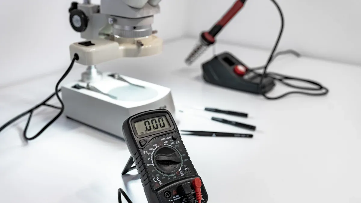
A digital multimeter is the most important tool for this task. You can use it to measure voltage, resistance, and check diode functions. Many multimeters also have a special socket for testing transistors, but you can still use the regular probes if yours does not. When you use a multimeter, you can test the pinout by measuring the voltage drop between pins. This helps you find the base, collector, and emitter.
Tip: Choose a multimeter that supports both ohmic (resistance) and diode modes. This gives you more options for testing.
Here are some features to look for in a multimeter:
Diode test mode and resistance mode.
Clear display for easy reading.
Good battery life for accurate results.
Firm and clean probes for solid contact.
Safety features like insulated probes.
When you use the multimeter, always turn off power to the circuit. Set the correct mode before testing. Connect the probes with the right polarity. Make sure you identify the pins using a datasheet or a clear reference image. This helps you avoid mistakes and keeps your components safe.
A reference image or datasheet is just as important as your multimeter. The datasheet shows the exact pin configuration. For the 2073, you will see pin 1 as the base, pin 2 as the collector, and pin 3 as the emitter. This information helps you avoid errors when you measure or build your circuit.
Note: Always compare your actual component with the datasheet or a trusted reference image. This step helps you confirm the pinout and prevents wiring mistakes.
Using a datasheet together with your multimeter makes your testing more accurate. You can check the pin functions by measuring resistance or voltage drop, then compare your results with the datasheet. This method improves your confidence and the reliability of your work.
Start by looking closely at your c2073 transistor. Hold the flat side of the package facing you, with the pins pointing down. You will see three pins lined up in a row. The metal tab at the top helps you find the correct orientation. The emitter pin usually sits closest to this metal tab.
Check for any markings on the body. You might see "c2073" or "2sc2073" printed on the front. These markings confirm you have the right npn transistor. If the print is hard to read, use a magnifying glass.
Tip: Always compare your transistor with a clear reference image or datasheet. This step helps you avoid mistakes before you start testing.
You can use a digital multimeter to check the pinout of your c2073 transistor. Set your multimeter to diode mode. This mode lets you measure the voltage drop between two pins.
Follow these steps:
Hold the transistor with the flat side facing you and pins down.
Touch the black probe to one pin and the red probe to another pin.
Record the reading. Swap the probes and test again.
Repeat this process for all pin pairs: 1-2, 1-3, and 2-3.
You want to find the base pin first. In an npn transistor like the c2073, the base will show a voltage drop (usually 0.6V to 0.7V) when you connect the red probe to the base and the black probe to the emitter or collector. If you reverse the probes, the reading should show "OL" (open loop) or no voltage drop.
Here is a simple table to help you:
| Test Pair | Red Probe | Black Probe | Expected Reading |
|---|---|---|---|
| Base - Emitter | Base | Emitter | 0.6V - 0.7V |
| Base - Collector | Base | Collector | 0.6V - 0.7V |
| Collector - Emitter | Collector | Emitter | OL or High |
Note: If you get a reading in both directions, your transistor may be faulty.
After you find the base, you need to confirm the collector and emitter. The collector usually connects to the metal tab at the top of the package. The emitter sits on the opposite side.
To confirm, place the red probe on the base and the black probe on each of the other two pins. The pin that gives a slightly higher voltage drop is the emitter. The other pin is the collector.
You can also check the datasheet for the c2073 pinout. The datasheet will show pin 1 as base, pin 2 as collector, and pin 3 as emitter when you look at the flat side with pins down.
Always double-check your results with a datasheet or trusted reference. This step keeps your circuit safe and prevents damage.
With these steps, you can identify the c2073 transistor pinout at home. You do not need special tools. A careful inspection and a simple multimeter test will help you work with confidence.
When you check a 2073 transistor pinout at home, you can avoid many common mistakes by following a few simple steps:
Verify the pins: Always check the transistor terminals using a datasheet or a trusted reference image. Use your multimeter to confirm the pinout before wiring.
Insert pins correctly: Place each transistor pin into a separate row on your breadboard. Never put two pins in the same column, or you might cause a short circuit.
Use a limiting resistor: Add a current-limiting resistor, such as a 1kΩ resistor, to the base pin. This protects both the transistor and your circuit.
Check biasing: Connect the base, collector, and emitter according to the transistor type and your circuit design. Proper biasing ensures the transistor switches as expected.
Double-check connections: Before you power your circuit, review all connections. A quick check can prevent costly mistakes.

 FPGA / CPLD
 Memory
 MOS
MOS  MCU
MCU  DSP
DSP OCEP
OCEP Secondary
  Other
Other