
075582814553

RF switches play a critical role in rf signal routing by directing signals between different paths in wireless and test systems. The rapid growth of mobile data and new technologies like 5G increase the demand for advanced rf switches to manage complex routing. For example, global mobile data traffic reached over 24 exabytes per month by 2019, and modern smartphones support many LTE bands, making rf switches more complex. High-performance rf switches help engineers control signal paths with low insertion loss and high isolation, which protects signal quality during routing. Accurate knowledge of these devices is essential for building reliable systems.
Modern rf signal routing often requires:
Low insertion loss and high isolation
Support for many frequency bands and standards
Reliable routing in high-power and multiport systems
RF switches, also known as radio frequency switch devices, control the path of high-frequency signals in electronic systems. These components play a vital role in signal management by directing signals between different circuits or devices. Engineers use rf switches in wireless communication, test equipment, and many other applications. The basic function of a radio frequency switch is to connect or disconnect signal paths, allowing for flexible rf signal routing.
Several common configurations exist for rf switches. The most basic type is the Single-Pole Single-Throw (SPST) switch, which acts like a simple on-off switch for one signal path. The Single-Pole Double-Throw (SPDT) switch can route a signal to one of two outputs. More complex designs, such as Double-Pole Double-Throw (DPDT) and multi-throw switches, support advanced routing and signal management needs. These configurations help engineers design systems that require multiple signal paths or need to switch between different antennas, test ports, or frequency bands.
Note: The choice of switch configuration depends on the application’s complexity and the number of signal paths required.
RF signal routing refers to the process of directing radio frequency signals through different paths within a system. This process is essential for devices like smartphones, base stations, and test instruments. Efficient rf signal routing ensures that signals reach their intended destination with minimal loss and interference.
Industry trends show that high-frequency rf switches now dominate the market, especially with the rise of 5G networks and advanced wireless systems. Consumer electronics, such as smartphones and IoT devices, rely on multiple radio frequency switch components to handle increasing data rates. The telecommunications sector leads in deploying rf switching products due to ongoing infrastructure upgrades. Automotive and industrial sectors also use these switches for telematics, automation, and robotics.
Performance metrics like insertion loss, isolation, and switching time validate the efficiency of rf signal routing. For example, a well-designed radio frequency switch can achieve low insertion loss and high isolation, which means less signal power is lost and less interference occurs between channels. Engineers often select rf switching products based on these metrics to ensure reliable routing and effective signal management.
Tip: Miniaturization and semiconductor advances, such as GaAs and SOI technologies, help create smaller, more efficient rf switches for modern applications.
Understanding rf switch specifications helps engineers select the right device for their application. Each parameter affects how the switch performs in real-world systems. The following sections explain the most important specifications and why they matter.
Insertion loss measures how much signal power is lost when the rf switch is in the ON state. Engineers express this value in decibels (dB). Lower insertion loss means more signal passes through the switch, which improves system performance. For example, the ADRF5144 switch shows an insertion loss of about 0.8 dB at 20 GHz with a 50 Ω load. If the return loss worsens, the insertion loss increases slightly, such as an extra 0.05 dB at 20 dB return loss and 0.45 dB at 10 dB return loss. These figures show that insertion loss depends on both the switch and the load conditions. In applications like transmit/receive switching, low insertion loss helps maintain signal integrity and reduces power loss.
Isolation describes how well the rf switch prevents unwanted signal leakage between its ports when it is OFF. High isolation keeps signals from crossing into other paths, which is important in systems with many channels. For instance, the ADRF5144 achieves 49 dB isolation at 20 GHz with a 50 Ω termination. High isolation protects sensitive receivers from interference and ensures clean signal routing. Engineers often look for high isolation in microwave switch designs used in test equipment and wireless infrastructure.
Return loss and Voltage Standing Wave Ratio (VSWR) both measure how well the rf switch matches the system impedance, usually 50 Ω. Good matching means less signal reflects back toward the source. Return loss is expressed in dB, with higher values indicating better matching. VSWR is a ratio, with values closer to 1:1 showing ideal matching. Poor return loss or high VSWR can cause extra insertion loss and reduce power transfer. For example, a return loss of 10 dB adds about 0.45 dB to the insertion loss. Engineers use these specifications to ensure efficient power transfer and minimize signal reflections.
Switching time tells how fast the rf switch can change from one state to another. Fast switching is important in high-speed systems like radar and test setups. Switching time includes both the transition time and any settling time needed for the signal to stabilize. Empirical data shows that some switches achieve transition times of about 6 nanoseconds (ns) for both high-to-low and low-to-high changes at a switching frequency of 250 MHz. Other devices show intrinsic switching times ranging from 600 picoseconds (ps) to 2.5 ns, with an average of 1.32 ns. Nearly half of tested devices switch in under 1 ns. These fast times are critical for applications that require rapid signal routing.
| Parameter | Value/Range | Description |
|---|---|---|
| Switching frequency | 250 MHz | Speed at which switching is measured |
| Transition time (high to low) | ~6 ns | Time to switch from ON to OFF |
| Transition time (low to high) | ~6 ns | Time to switch from OFF to ON |
| Intrinsic switching time | 600 ps – 2.5 ns | Range across devices |
| Mean switching time | 1.32 ns | Average across devices |
| Percentage sub-ns switching | ~46% | Devices with <1 ns switching |
Frequency range, or bandwidth, defines the span of frequencies over which the rf switch operates effectively. A broad frequency range allows the switch to support more applications, such as multi-band wireless systems and test equipment. For example, UltraCMOS SOI switches work from 1.002 GHz to 1.794 GHz in DOCSIS 3.1 cable modems, maintaining high linearity and low harmonic distortion. RF front-end switches for advanced base stations operate up to 6 GHz, supporting high power handling and fast switching. Some phase shifters show insertion loss below 0.5 dB at 3.8 GHz and high linearity (IIP3 > 85 dBm). Silicon-based SOI technology enables integration of multiple rf functions for frequencies below 6 GHz. Engineers must balance frequency range with other specifications, as performance can change across the band.
Series-type switches offer good isolation and insertion loss at low frequencies but degrade at higher frequencies.
Parallel-type switches suit narrowband, high-frequency uses but cost more.
Series-parallel topologies balance insertion loss, isolation, and power handling across a wide band (6–18 GHz).
Absorptive switch designs improve high power handling by terminating the off-state port, reducing damaging reflections.
Power handling shows how much signal power the rf switch can manage without damage or performance loss. High power handling is vital in transmit paths, radar, and base station systems. For example, a directional coupler tested at 50 W input power and 5.7 GHz showed stable insertion loss and return loss, proving reliable operation at high power. Theoretical limits for some materials reach up to 800 MW, but practical limits depend on connectors and system design. Power handling also depends on load impedance and connector quality. Some switches, like those in high power rf switch designs, handle up to 500 W, while others are limited to 1 W. Engineers must consider temperature rise and heat dissipation, as excessive heat can damage the switch. Specifications like P1dB (1 dB compression point) and PIP3 (third-order intercept point) help define safe operating levels.
| Parameter | NI PXI-2557 (2.5 GHz, 75 Ω) | Other PXI Vendor (3 GHz, 75 Ω) |
|---|---|---|
| Insertion Loss at 3 GHz (dB) | 1.78 | 5.64 |
| Voltage Attenuation (%) | 18.3 | 47.8 |
| Power Loss (%) | 33.3 | 72.7 |
Repeatability means the rf switch performs the same way every time it operates. Settling time is the period after switching when the signal stabilizes. Mechanical switches often have a settling time of 12–15 milliseconds due to contact bounce, with switching times around 8–9 milliseconds. Over many cycles, mechanical contacts can wear out, reducing repeatability in insertion loss and phase. Solid-state switches, such as those in microwave switch designs, have no moving parts and switch almost instantly, with no settling time. These switches offer better repeatability and longer life. Calibration and careful measurement can improve repeatability, reducing errors from 0.25 dB to 0.01 dB in some tests.
Impedance, usually 50 Ω, must match the rest of the system to prevent reflections and power loss. Linearity measures how well the rf switch handles large signals without distortion. High linearity is important in systems that process many signals at once, such as base stations and cable modems. For example, UltraCMOS SOI switches meet strict DOCSIS 3.1 linearity standards, with second and third harmonics far below required limits. High linearity ensures the switch does not add unwanted signals or noise, protecting signal integrity. Engineers must check these specifications to ensure the switch fits the system’s needs.
Tip: No single rf switch design meets all application requirements. Engineers must balance bandwidth, power handling, linearity, switching speed, insertion loss, and isolation to match their system’s needs.
Electromechanical relay switches use moving metal contacts to open or close a circuit. These switches provide low insertion loss and good isolation, making them ideal for high power rf switch applications. They can handle large amounts of power and voltage, which is important in test systems and broadcast equipment. Electromechanical relay switches also offer high immunity to electrostatic discharge and can survive harsh electrical environments. However, they switch slowly, often taking several milliseconds, and their mechanical parts wear out over time. This limits their operating life to about five million cycles. They are also larger and heavier than other types.
| Parameter | Electromechanical RF Switches | Solid-State RF Switches |
|---|---|---|
| Insertion Loss | Low | Higher |
| Isolation | Good, galvanic isolation | Excellent, no galvanic barrier |
| Switching Speed | Slow (ms) | Fast (ns) |
| Power Handling | High | Lower |
| Operating Life | Limited (mechanical wear) | Very long (no moving parts) |
Note: Electromechanical relay switches work best in high voltage, high power, and surge current environments.
Solid-state radio frequency switch designs use semiconductor devices like PIN diodes and FETs. These switches have no moving parts, so they last much longer and switch much faster than electromechanical types. PIN diode switches offer very fast switching and low insertion loss, which helps in high power rf switch systems. They can handle high frequencies and power levels, but they need more current and have a larger circuit footprint. FET switches, especially those made with GaAs or SOI technology, use less power and fit into smaller spaces. They provide broadband coverage and high linearity, but they have higher insertion loss and slower switching than PIN diodes. Solid-state switches are common in wireless devices, satellite communications, and test equipment. They do not provide galvanic isolation and can be sensitive to power surges.
Tip: Solid-state switches work well in fast switching, low power, and compact applications, but engineers must manage heat and avoid overstress.
High power rf switches stand out because they can handle much greater power levels than standard designs. These switches appear in radar, broadcasting, and military systems where signal strength is high. High power rf switches can be either electromechanical or solid-state, but many use special materials and designs to improve performance. For example, some high power rf switches use aluminum alloy membranes or advanced dielectrics to achieve low insertion loss (as low as 0.25 dB at 35 GHz) and high isolation (over 25 dB up to 40 GHz). Engineers use simulation tools like FEM and MoM to test these designs. High power rf switches must also manage heat and avoid signal distortion. Reliability issues, such as stiction and dielectric charging, can affect some types, but new designs help reduce these problems.
High power rf switches support:
Power levels from tens to thousands of watts
Wide frequency ranges, sometimes up to 40 GHz
Low insertion loss and high isolation for signal quality
A microwave switch used as a high power rf switch must balance power handling, speed, and reliability. Engineers choose the right radio frequency switch based on the needs of the system, such as power, speed, and size.
RF switches serve a wide range of applications across many industries. Their ability to control high-frequency signals makes them essential for modern technology. The following sections highlight the main areas where these devices play a key role.
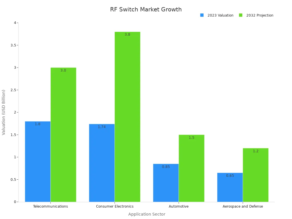
Wireless systems rely on RF switches for efficient signal routing and connectivity. These switches appear in mobile phones, Wi-Fi routers, Bluetooth devices, and GPS systems. They help manage multiple frequency bands and antennas, which improves communication quality. The global RF switches market reached about $4.36 billion in 2024 and is expected to grow to $7.39 billion by 2033. This growth shows the rising demand for RF switches in wireless applications. The table below shows how different sectors use these switches:
| Application Sector | 2023 Value (USD Billion) | 2032 Value (USD Billion) | Key Role in Wireless Systems |
|---|---|---|---|
| Telecommunications | 1.8 | 3.0 | Manage high-frequency signals for 5G and wireless communication |
| Consumer Electronics | 1.74 | 3.8 | Enhance smart device connectivity and IoT support |
| Automotive | 0.85 | 1.5 | Enable navigation and safety features through wireless links |
| Aerospace and Defense | 0.65 | 1.2 | Ensure secure, reliable communication in critical systems |
Test and measurement applications depend on RF switches for accurate and flexible testing. Laboratories and factories use these switches in automated test systems to measure the performance of transmitters and receivers. For example, a typical RF switch used in testing offers up to 8 channels, supports frequencies from 10 MHz to 8 GHz, and provides high isolation and low insertion loss. Companies like Ranatec and National Instruments design switch modules that help engineers test products from early design to mass production. These applications require reliable signal routing to ensure precise results.
RF switches support many other applications beyond wireless and testing. In radar systems, they allow fast switching between transmit and receive modes. Medical imaging devices, such as MRI and ultrasound machines, use them to select different signal paths. The automotive industry uses RF switches in radar for collision avoidance and adaptive cruise control. Industrial automation, process control, and research labs also rely on these devices for signal management and quality control. RF switches even appear in video routing for studios and surveillance systems. Their versatility makes them valuable in many fields.
Note: The broad range of applications for RF switches highlights their importance in modern electronics and communication systems.
Selecting the right RF switch starts with understanding the system’s requirements. Engineers should follow a clear process to match the switch to the application.
1. Identify the RF circuit type needed, such as SPDT or DPDT, based on how many signal paths the system must control.
2. Choose the actuator type, like pulse latching or failsafe, to match power needs and safety features.
3. Set the minimum frequency or bandwidth required for the application. A switch must support the full bandwidth of the signals to avoid distortion or loss.
4. Confirm the actuator voltage matches the system’s power supply.
5. Decide on the polarity option, either positive or negative common, to fit the system design.
6. Select the power interface, such as solder terminals or connectors, for easy integration.
Engineers must check that the switch’s characteristic impedance, usually 50 Ω, matches the system. This prevents signal reflections and protects equipment. Proper termination keeps impedance stable and avoids damage. Switching active RF signals can cause problems, so engineers should avoid this practice. When switching low-level signals, the relay type matters because electromechanical relays may not perform well.
Performance specifications like insertion loss, isolation, and return loss must meet the system’s needs. Engineers should also check the switch’s bandwidth to ensure it covers all signal frequencies. High isolation and low crosstalk keep signals clean. Rise time and -3 dB bandwidth help confirm the switch can handle signals with many frequency components.
Reliability is important. High-reliability switches last longer and reduce downtime. Repeatability in insertion loss and phase ensures accurate measurements and lowers calibration costs.
Engineers should consider connector types, packaging, and cost when choosing an RF switch. The table below shows common connector options and their features:
| Connector Type | Frequency Range | Packaging Options | Key Features & Applications |
|---|---|---|---|
| MCX | DC to 6 GHz | Single, trays, tape-reel | Small, easy mating, wireless devices |
| MMCX | DC to 6 GHz | Similar to MCX | Compact, used in small wireless products |
| TLMP | DC to 60 GHz | Not specified | High vibration resistance, aerospace |
| 0.9 mm SuperMini | Up to 110 GHz | Not specified | Lightweight, aerospace, UAVs |
| X.FL | Up to 12 GHz | Tape carrier reels | Low-profile, WiGig applications |
Packaging affects cost and assembly. Automated packaging, like tape-and-reel, supports fast manufacturing. Miniaturized connectors save space in compact devices. Manufacturing methods, such as CNC machining or stamping, also impact cost and durability.
Material choices and switch structure affect performance. For example, thicker dielectric layers can lower insertion loss but may increase power use. Engineers must balance these trade-offs to meet both performance and budget goals.
Cost depends on technical performance. Lower insertion loss reduces power use and heat, saving money. High isolation improves reliability, which cuts maintenance costs. High power handling allows use in many applications, making the switch more cost-effective.
Tip: Always review the switch’s specifications and bandwidth in detail. Consult datasheets or vendors to ensure the switch meets all system requirements.
Understanding the key specifications and types of RF switches helps engineers build reliable and high-performing systems. Careful selection improves signal routing and supports many applications, from wireless networks to test equipment. Case studies show that optimizing metrics like insertion loss, isolation, and switching speed leads to better electrical performance and longer switch life. The table below highlights how these metrics benefit system design:
| Performance Metric | Case Study Benefit |
|---|---|
| Insertion Loss | Low signal loss, better than -0.5 dB in ON state |
| Return Loss | Good impedance match, less than -10 dB in ON state |
| Isolation | Excellent separation, about -43 dB at 27 GHz in OFF state |
| Switching Speed | Fast response, critical for dynamic systems |
| Power Consumption | Lower energy use, improved reliability |

 FPGA / CPLD
 Memory
 MOS
MOS  MCU
MCU  DSP
DSP OCEP
OCEP Secondary
  Other
Other