
075582814553

The Hartley oscillator, named after its inventor Ralph Hartley in 1915, stands as a cornerstone in the field of electronic oscillators. Famous for its simple, yet effective design, this oscillator utilizes a basic LC circuit configuration to generate stable sinusoidal waveforms, making it requisite in radio frequency applications. Its operational principle is based on the strategic use of inductors and capacitors to sustain oscillations, complemented by an active component for amplification. This article digs into the detailed workings of the Hartley oscillator, exploring its various configurations, including transistor-based and op-amp versions, and extending to its practical applications in modern electronic systems.

The Hartley oscillator, developed by Ralph Hartley in 1915, is a basic electronic circuit used to generate sinusoidal waveforms. It relies on an LC circuit, a combination of inductors and capacitors, to establish and sustain oscillations. Due to its simple design, reliability, and adaptability, it remains a widely used choice in radio frequency (RF) applications.
At the heart of the Hartley oscillator is its LC circuit, which determines the oscillation frequency. This frequency depends on the electrical characteristics of its inductors and capacitors. The circuit typically consists of a single inductor with a center tap and two capacitors. An active component—such as a transistor or vacuum tube—is responsible for amplifying and sustaining the oscillations by providing positive feedback. This feedback ensures that a portion of the output signal is redirected back into the system as input, allowing the oscillations to continue indefinitely.
The oscillator's frequency can be finely adjusted by modifying the values of the capacitors and the inductor, allowing precise control over the output signal. This flexibility makes it suitable for a broad range of RF applications where frequency stability and tunability are needed.
The Hartley oscillator relies on positive feedback to sustain a continuous oscillating signal. At its core, it features a resonant LC circuit, where inductors and capacitors work together to establish oscillations at a specific frequency. This frequency is determined by the circuit’s component values and resonance properties. The cyclic exchange of energy between the inductors and capacitors creates an alternating high and low impedance state, ensuring efficient energy transfer throughout the circuit.
For the oscillator to function, a portion of the output signal is fed back into the input. In transistor-based designs, this feedback is drawn from the collector (or the drain in field-effect transistors) and directed back to the base (or gate) through a tapped coil or feedback transformer. This feedback signal must be precisely phase-aligned with the input to maintain positive reinforcement, allowing oscillations to continue without external intervention.
The active component, typically a transistor or vacuum tube, plays a key role as an amplifier. It strengthens the oscillatory signal, continuously replenishing energy lost due to resistance and other circuit inefficiencies. The active component maintains a stable and sustained oscillatory output by integrating the signals from the LC circuit with the feedback loop.
When power is first applied, minor disturbances—such as thermal noise or inherent fluctuations within the circuit—initiate the oscillations. Once started, these oscillations naturally stabilize at the resonant frequency determined by the inductor and capacitor values. However, external factors like temperature changes or component variations can affect performance. To ensure reliable operation, careful component selection and precise circuit design are required.
By balancing feedback strength, component values, and circuit conditions, the Hartley oscillator achieves a steady and controllable output, making it a valuable tool in RF applications, signal generation, and communication systems.

Figure 2. Hartley Oscillator Circuit Using an Op-Amp
In modern electronic designs, an operational amplifier (op-amp) is often used in Hartley oscillator circuits to enhance stability and gain control. This approach provides a consistent output signal by minimizing fluctuations in gain, which can be an issue in transistor-based versions. The design process involves adjusting feedback and input resistances to ensure the op-amp delivers sufficient gain to sustain oscillations over a defined frequency range.
In transistor-based Hartley oscillators, the gain depends on the components of the tank circuit, making it more susceptible to variations in component values. By contrast, an op-amp-based design maintains a steady gain, improving frequency accuracy and reducing unwanted deviations. The feedback loop in both configurations works similarly, generating a sine wave. However, in the op-amp version, the amplifier stabilizes and inverts the signal, ensuring a well-regulated output.
The oscillation frequency is determined by the equation:
fo = 1/(2π√LeqC)
where Leq represents either L1 + L2 or L1 + L2 + 2M if mutual inductance (M) between the inductors is considered. To enable and maintain oscillations, the amplifier’s gain (Av) must be at least equal to the inductance ratio L1/L2, with further adjustments to account for mutual inductance.
For fine-tuning the oscillator's frequency, a variable capacitor in the tank circuit allows precise modifications, making the circuit adaptable for different applications. By carefully calibrating both gain and frequency settings, the op-amp-based Hartley oscillator achieves reliable and stable oscillatory performance, making it a valuable choice for precision signal generation and RF applications.

Figure 3. Shunt-Fed Hartley Oscillator
The shunt-fed Hartley oscillator is designed to generate high-frequency signals with improved stability and frequency accuracy. Unlike standard Hartley oscillator configurations, this design places an inductor in parallel with a capacitor, forming a resonant LC tank circuit. This setup helps maintain a consistent oscillation frequency, making it a preferred choice for RF circuits, signal generators, and communication systems where precise frequency control is a must.
In this configuration, the resonant frequency is determined by the values of the shunt inductor and capacitor. This arrangement not only sustains oscillations efficiently but also enhances frequency stability compared to other oscillator designs. Because the shunt-fed structure reduces variations caused by component tolerances, it offers greater fidelity in maintaining the intended frequency over the extended operation.
Due to its efficiency and straightforward design, the shunt-fed Hartley oscillator is commonly used in applications that require stable high-frequency signals with minimal drift. The design also allows for easier tuning and adjustments, making it adaptable for different frequency ranges.
Understanding the frequency characteristics of a Hartley oscillator involves analyzing the reactances within the circuit. Specifically, the inductive reactances (Z1 and Z2) and the capacitive reactance (Z3) play a major role in forming the feedback loop that sustains oscillations.
By incorporating these reactance values into the standard oscillator formula, the resonant frequency can be accurately calculated. This analysis demonstrates how oscillator theory is directly applied in practical circuit design. Example calculations using specific component values highlight the circuit’s effectiveness in actual applications, reinforcing its role in precision signal generation.
The Hartley oscillator is widely used in electronic systems that require stable and precise frequency generation. Its ability to produce consistent oscillations makes it a key component in radio transmitters, receivers, and signal generators. These oscillators are useful in RF modulation and frequency synthesis, where they help generate and maintain carrier signals for communication systems.

Figure 4. Radio and Communication Systems
In radio transmission and reception, Hartley oscillators are used to generate carrier frequencies and support frequency conversion in superheterodyne receivers. Their stable frequency output is used for minimizing signal distortion and ensuring clear communication.
They also play an active role in frequency synthesizers and phase-locked loops (PLLs), where they provide stable reference signals for precise channel selection and synchronization in modern communication systems. These functions are useful in applications such as wireless communication, broadcasting, and satellite navigation.
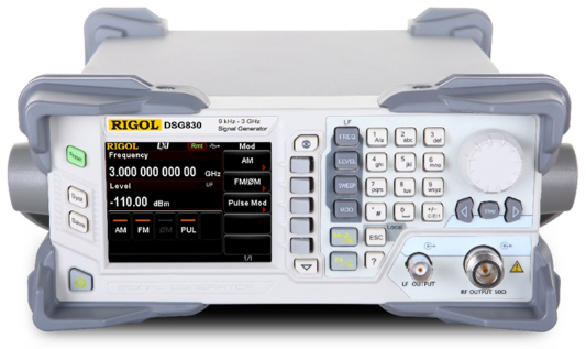
Figure 5. Signal Generator
Hartley oscillators are commonly found in signal generators, which are serious for testing, calibrating, and analyzing electronic circuits. Their reliable performance ensures accurate waveform generation, making them valuable in laboratories, manufacturing, and diagnostic equipment.

Figure 6. RF Amplification
Additionally, these oscillators improve the performance of RF amplification and filtering systems, enhancing the efficiency of radar, wireless transmitters, and RF front-end modules. Their ability to maintain frequency stability helps optimize signal integrity, which is used for high-performance communication and sensing technologies.
By providing stable and tunable frequency outputs, the Hartley oscillator remains a basic building block in modern electronics, supporting advancements in communication, testing, and signal processing technologies.
• Simple and Efficient Design: The Hartley oscillator is valued for its simple and efficient design, requiring only a few passive components along with an active amplifying device. This simplicity makes it easy to build, modify, and maintain, making it a popular choice in RF and communication applications.
• Wide Frequency Range: One of its key strengths is its ability to operate over a wide frequency range while maintaining reasonable stability. The oscillator's tuning flexibility allows precise frequency adjustments by modifying the inductor or capacitor values, making it well-suited for signal generation, frequency synthesis, and modulation tasks.
Despite its advantages, the Hartley oscillator has limitations that can affect its performance in certain applications.
• Frequency Instability: One major challenge is frequency instability, which can be influenced by temperature changes, component aging, and variations in supply voltage. These factors may cause slight shifts in the oscillation frequency, requiring careful circuit design and shielding to minimize their impact.
• Lower Power Output: The Hartley oscillator typically has a lower power output, making it less suitable for high-power transmission applications without additional amplification. Another potential issue is the generation of unwanted harmonics, which can lead to interference and signal distortion. To maintain signal purity, filtering and fine-tuning techniques are often necessary, adding complexity to the design.
Throughout its wide exploration, the Hartley oscillator reaffirms its legacy as a versatile and robust component in electronic circuit design. From its basic operational dynamics to advanced configurations like the shunt-fed version, the oscillator's ability to provide precise frequency control makes it invaluable in RF applications and signal generation. Despite some challenges related to frequency stability and power output, its advantages in terms of simplicity and tunability continue to make it a preferred choice for radio transmissions, signal processing, and communication systems. By understanding both its capabilities and limitations, you can effectively harness the Hartley oscillator to meet the evolving demands of modern electronic technologies.

 Catalogue
 FPGA / CPLD
 Memory
 MOS
 MCU
 DSP
 OCEP
 Secondary
 Other


