
075582814553

A varactor diode is a special type of semiconductor diode used in electronic circuits where adjustable capacitance is required for tuning and frequency control. It provides a compact and efficient way to electronically adjust circuit behavior without using mechanical components. Unlike standard diodes used for rectification, varactor diodes are designed specifically for controlled capacitance variation, making them an important component in modern wireless and high-frequency electronics. This article will discuss the working principle, internal structure, key specifications, different types, applications, and performance characteristics of varactor diodes.
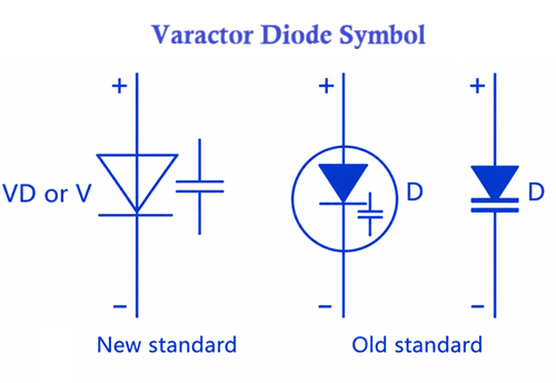
A varactor diode is a voltage-controlled capacitor designed to operate specifically in reverse bias mode. Unlike a standard diode used for rectification, its main function is not to conduct current but to vary capacitance based on the applied reverse voltage. This makes it a key component in RF tuning, frequency control, and communication systems.
Inside the device, the P-type and N-type regions form a PN junction. When reverse bias is applied, a depletion region forms between these two regions. This depletion region behaves as an effective dielectric layer, while the P and N regions act like capacitor plates. As a result, the varactor diode behaves like a capacitor whose value changes with voltage.
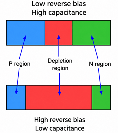
For proper operation, a varactor diode must always be reverse biased. In this condition, current flow is minimal, and the applied voltage directly controls the width of the depletion region.
When the reverse voltage is low, the depletion region becomes narrow, meaning the effective distance between charge regions is small and the capacitance is high. As the reverse voltage increases, the depletion region widens, increasing the separation and reducing the capacitance. This inverse relationship between voltage and capacitance is the core operating principle of the device.
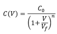
The relationship between capacitance and reverse bias voltage is nonlinear and can be described using the standard varactor diode equation:
Where:
• C(V) = capacitance at applied reverse voltage
• C₀ = zero-bias junction capacitance
• V = applied reverse bias voltage
• Vf = built-in junction potential
• n = grading coefficient (typically 0.3 to 0.5 depending on diode type)
For an abrupt junction varactor, the value of n ≈ 1/2, while hyperabrupt varactors have different values that produce a steeper capacitance change.
This equation explains why capacitance decreases rapidly at lower voltages and more gradually at higher voltages, as shown in typical C–V characteristic curves.
How the capacitance of a varactor diode changes as the reverse bias voltage increases? As shown in the graph, capacitance is highest at low reverse voltage and gradually decreases as the reverse voltage becomes more negative. This relationship is fundamental to how varactor diodes operate as voltage-controlled capacitors in RF and communication circuits.
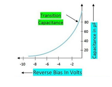
This behavior occurs because the depletion region inside the PN junction acts as the dielectric of a capacitor. When reverse bias is applied, the depletion region forms between the P-type and N-type materials. At low reverse voltage, the depletion region is narrow, meaning the effective distance between charge regions is small, resulting in higher capacitance. As the reverse voltage increases, the depletion region widens, increasing the separation and reducing the capacitance.
As clearly shown in the image, the capacitance response is nonlinear, meaning it does not decrease at a constant rate but follows a curved transition profile. This characteristic is essential for frequency tuning applications, where small changes in voltage can produce controlled shifts in capacitance.
This voltage-dependent capacitance allows circuits to electronically adjust tuning behavior without mechanical components. Instead of using a variable capacitor, a DC control voltage is applied to the varactor diode
The image below shows the internal construction of a mesa-type Gallium Arsenide (GaAs) varactor diode. A varactor diode is specially designed to provide a controlled change in capacitance when operated under reverse bias. Its construction is optimized to achieve stable capacitance characteristics at high frequencies.
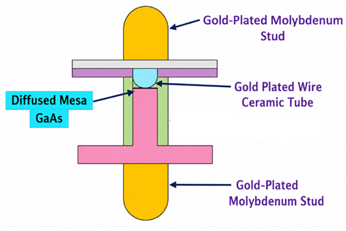
• Diffused Mesa GaAs Junction - At the center of the device is the diffused mesa GaAs junction, which forms the active region of the varactor diode. This PN junction is where the depletion region develops when reverse voltage is applied. As the reverse voltage changes, the width of the depletion region changes, causing the junction capacitance to vary. Gallium Arsenide (GaAs) is often used in high-frequency and microwave applications because of its excellent electrical performance and low parasitic losses.
• Gold-Plated Wire - The gold-plated wire provides the electrical connection between the semiconductor junction and the external terminal. Gold is commonly used because it offers low electrical resistance, excellent conductivity, and high resistance to corrosion. This helps maintain reliable electrical performance over time.
• Ceramic Tube - The ceramic tube acts as an insulating and supporting structure for the internal components. It provides mechanical stability and electrical isolation while protecting the semiconductor junction from environmental factors such as moisture, contamination, and mechanical stress.
• Gold-Plated Molybdenum Studs - The upper and lower terminals are gold-plated molybdenum studs. These studs serve as the external electrical connections of the diode. Molybdenum is chosen because its thermal expansion properties are compatible with semiconductor materials, helping reduce mechanical stress during temperature changes. The gold plating improves conductivity and protects the surface from oxidation.
The semiconductor junction is mounted between the metal studs and connected through the bonding wire. When a reverse-bias voltage is applied across the terminals, a depletion region forms inside the junction. The P-type and N-type regions act as capacitor plates, while the depletion region acts as the dielectric. By changing the reverse voltage, the capacitance of the diode changes, allowing the varactor diode to function as a voltage-controlled capacitor.
When selecting a varactor diode, several electrical parameters determine its tuning performance, frequency range, efficiency, and suitability for a particular RF or microwave application.
Capacitance range indicates the minimum and maximum capacitance that the varactor diode can provide across its specified reverse voltage range.
Typical values:
• Low-capacitance RF varactors: 0.3 pF to 10 pF
• General tuning varactors: 2 pF to 100 pF
• High-capacitance tuning varactors: 20 pF to 500 pF
• Special applications: up to 1000 pF
A wider capacitance range generally allows a larger tuning range in oscillators and resonant circuits.
The tuning ratio describes how much the capacitance changes between the minimum and maximum operating voltages.
Tuning Ratio = Maximum Capacitance ÷ Minimum Capacitance
Typical values:
• Standard abrupt-junction varactors: 2:1 to 5:1
• Hyperabrupt varactors: 5:1 to 15:1
• Specialized microwave varactors: up to 20:1
Higher tuning ratios provide greater frequency adjustment capability.
Reverse breakdown voltage specifies the maximum reverse voltage that can be applied before the junction begins conducting heavily.
Typical values:
• Low-voltage varactors: 8 V to 20 V
• General-purpose varactors: 20 V to 50 V
• High-voltage tuning varactors: 50 V to 150 V
Designers typically operate the diode well below its breakdown rating for reliability.
The Q factor measures how efficiently the varactor stores energy compared to the energy it dissipates.
Typical values:
• Standard RF varactors: 50 to 200
• High-performance RF varactors: 200 to 500
• Microwave varactors: 500 to 2000+
Higher Q values produce lower losses and better performance in oscillators, filters, and resonant circuits.
Series resistance, often called Rs, represents the internal resistance of the diode.
Typical values:
• Microwave varactors: 0.1 Ω to 2 Ω
• RF tuning varactors: 1 Ω to 10 Ω
• General-purpose devices: up to 20 Ω
Lower series resistance improves Q factor and reduces power loss.
Capacitance tolerance indicates how closely the actual capacitance matches the specified value.
Typical values:
• Precision varactors: ±2% to ±5%
• Standard varactors: ±10%
• General-purpose devices: ±20%
Tighter tolerances are preferred in frequency-sensitive circuits.
Varactor diodes are designed primarily for RF and microwave applications.
Typical ranges
• AM/FM radio tuning: 500 kHz to 200 MHz
• VHF/UHF systems: 30 MHz to 3 GHz
• Cellular and wireless systems: 800 MHz to 6 GHz
• Microwave and radar systems: 6 GHz to 100 GHz+
The maximum usable frequency depends on the diode's package parasitics, capacitance value, and Q factor.
Temperature stability describes how much capacitance changes with temperature.
Typical operating temperature ranges:
• Commercial grade: 0°C to +70°C
• Industrial grade: −40°C to +85°C
• Extended industrial grade: −55°C to +125°C
Typical capacitance temperature coefficient:
• 50 ppm/°C to 1000 ppm/°C, depending on device construction and materials.
Abrupt junction varactor diodes use a sharply defined PN junction with a relatively sudden change in doping concentration. Their capacitance changes smoothly as reverse voltage increases, but the tuning range is usually moderate. A typical abrupt junction varactor may offer a tuning ratio of about 2:1 to 5:1, with capacitance values commonly ranging from 1 pF to 200 pF.
Hyperabrupt junction varactor diodes use a specially graded doping profile that allows capacitance to change more strongly with reverse voltage. This gives them a much wider tuning range than abrupt junction types. Their tuning ratio is typically around 5:1 to 15:1, and some specialized devices can go higher. Capacitance values often range from about 0.5 pF to 100 pF.
Silicon varactor diodes are the most common type used in commercial RF circuits. They are affordable, stable, and widely available in many capacitance and voltage ratings. Typical silicon varactors may have capacitance values from 1 pF to 500 pF, reverse breakdown voltages from 8 V to 100 V, and operating frequencies from hundreds of kHz to several GHz, depending on the package and device design.
Gallium Arsenide, or GaAs, varactor diodes are designed for higher-frequency and microwave applications. GaAs provides better high-frequency performance than standard silicon because it has higher electron mobility and lower parasitic losses. These varactors often operate from around 1 GHz to over 100 GHz, depending on the device structure. They usually have low capacitance values, often below 10 pF, and low series resistance for better Q factor.
Dual varactor diodes contain two matched varactor diodes in one package. This structure helps improve capacitance matching and tracking accuracy between the two junctions. Typical capacitance values may range from 2 pF to 50 pF per diode, depending on the model. Dual varactors are useful when two tuning elements must change together with the same control voltage.
High-Q varactor diodes are designed for low loss and high energy efficiency in resonant circuits. The Q factor shows how well the diode stores energy compared with how much energy it loses. Standard RF varactors may have Q values around 50 to 200, while high-Q varactors can reach 200 to 2000 or higher at specified test frequencies. These devices usually have low series resistance, often below 1 Ω to 5 Ω.
Microwave varactor diodes are made for circuits that operate at microwave and millimeter-wave frequencies. They usually have very small capacitance values, often from 0.1 pF to 10 pF, to reduce parasitic effects at high frequencies. Their operating range can extend from about 3 GHz to 100 GHz or more, depending on the package and material.
Tuning varactor diodes are general-purpose varactors used for electronic frequency adjustment. They are designed to replace mechanical variable capacitors in many consumer and communication circuits. Typical capacitance ranges are around 2 pF to 100 pF, with reverse voltage ratings commonly between 20 V and 50 V.
• Voltage-Controlled Oscillators (VCOs) – Varactor diodes are used to electronically adjust oscillator frequency by varying capacitance with a control voltage.
• Phase-Locked Loop (PLL) Circuits – Provide precise frequency tuning and stabilization in communication and clock-generation systems.
• Frequency Synthesizers – Varactor diodes enable the generation of multiple frequencies from a single reference source in radios and wireless equipment.
• FM Radio Tuners – Replace mechanical variable capacitors for electronic station tuning and automatic frequency control.
• Television Tuners – Varactor diodes allow electronic channel selection and frequency adjustment in analog and digital television receivers.
• RF Filters – Provide tunable filter characteristics by changing the resonant frequency of LC filter networks.
• Wireless Communication Equipment – Used in transceivers, receivers, and transmitters for frequency control and signal tuning.
• Satellite Communication Systems – Varactor diodes support microwave frequency tuning, filtering, and signal processing functions.
• Radar Systems – Used in microwave oscillators, phase shifters, and frequency control circuits operating at high frequencies.
• Military and Aerospace Electronics – Applied in advanced radar, communication, and electronic warfare systems requiring precise frequency control.
• Medical RF Equipment – Used in specialized imaging, monitoring, and wireless medical communication systems.
• Internet of Things (IoT) Devices – Varactor diodes support compact RF tuning and frequency control functions in wireless sensors and connected devices.
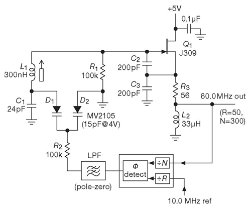
The varactor diodes D1 and D2 are connected within the VCO tuning network. The PLL's phase detector compares the output frequency with the reference frequency and generates an error signal. After passing through the loop filter, this control voltage is applied to the varactor diodes through resistor R2.
As the control voltage changes, the capacitance of the varactor diodes changes. This alters the resonant frequency of the LC tank circuit formed by L1, C1, and the varactors. The oscillator frequency therefore increases or decreases until the PLL locks to the desired frequency.
Once locked, the PLL continuously adjusts the varactor capacitance to maintain a stable output frequency despite temperature changes, supply variations, or component drift.
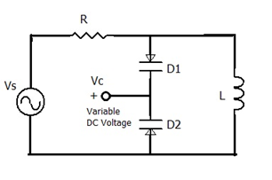
In this circuit, varactor diodes D1 and D2 are connected as voltage-controlled capacitors. A variable DC voltage (Vc) is applied to the varactors, changing their junction capacitance. Together with the inductor L, the varactors form a tunable LC resonant circuit.
When the tuning voltage changes, the capacitance of the varactor diodes changes, shifting the resonant frequency of the circuit. This allows the filter to electronically tune to different frequencies without using a mechanical variable capacitor.
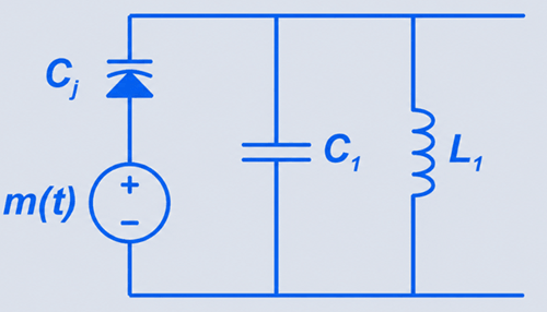
This circuit uses a varactor diode as a voltage-controlled capacitor. The signal m(t) changes the reverse-bias voltage across the varactor diode.
When the reverse voltage changes, the varactor’s junction capacitance Cj also changes. This capacitance works with L1 and C1 to form an LC resonant circuit.
When Cj increases, the resonant frequency decreases. When Cj decreases, the resonant frequency increases. Because the modulation signal continuously changes the capacitance, the output frequency varies with the signal. This produces frequency modulation (FM).
Varactor diodes are available in different series depending on capacitance range, tuning ratio, reverse voltage rating, and frequency performance.
The BB109 is a widely used silicon varactor diode designed for FM radio tuning and general RF applications. It typically offers a capacitance range of around 10 pF to 30 pF, with a reverse voltage rating of approximately 1 V to 30 V. Its tuning ratio is moderate, making it suitable for VHF receivers, RF filters, and simple VCO circuits. It is known for stable performance in low-power analog tuning systems.
The BB112 is a higher-capacitance varactor diode commonly used in TV tuners and communication receivers. It provides a capacitance range of about 12 pF to 500 pF, depending on bias voltage, with a reverse breakdown voltage around 30 V to 60 V. It offers a higher tuning ratio than BB109.
The BBY51 is a low-capacitance, high-frequency varactor diode designed for UHF and microwave applications. It typically operates with capacitance values from 1 pF to 6 pF, and supports high-frequency operation up to several GHz. It is commonly used in VCOs, phase-locked loops, and RF front-end modules where low loss and high Q factor are required.
The SMV1231 series is a modern silicon hyperabrupt varactor family optimized for RF tuning applications. It typically provides capacitance ranges from 2 pF to 20 pF, with reverse voltages up to 30 V to 50 V.
The SMV1247 series is designed for broader tuning applications requiring higher capacitance variation. It offers capacitance values from approximately 10 pF to 100 pF, with excellent tuning ratios reaching 10:1 or higher.
The MV2105 is a classic silicon varactor diode often used in analog tuning circuits. It provides a capacitance of around 15 pF at 4 V bias, making it suitable for VHF oscillators and FM modulation circuits.
The 1SV149 is a compact varactor diode designed for high-frequency applications such as mobile communication systems. It typically supports capacitance values from 2 pF to 10 pF, with low series resistance and good Q factor performance.
The KV1235 series consists of microwave-grade varactor diodes designed for high-performance RF and satellite systems. These diodes operate in the GHz frequency range, typically from 1 GHz up to 20+ GHz, depending on the configuration. They offer low capacitance, high Q factor, and low parasitic losses.
A varactor diode and a variable capacitor both serve the same functional purpose of providing adjustable capacitance. But their operating principles are fundamentally different. A varactor diode is a semiconductor device that changes its capacitance electronically. This variation occurs when a reverse-bias voltage alters the width of the depletion region within the PN junction. Since this process is purely electronic, the device has no moving parts, making it compact, fast, and highly suitable for integration into modern RF circuits.
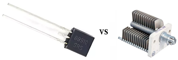
In contrast, a variable capacitor achieves capacitance adjustment through mechanical movement of conductive plates. By changing the distance or overlapping area between these plates, the capacitance value is physically modified. While this mechanical approach provides very stable and linear capacitance behavior, it also makes the component larger, slower, and more prone to wear over time.
A MEMS tunable capacitor is based on micro-electromechanical system technology, where microscopic mechanical structures fabricated on silicon chips physically move to adjust capacitance. Unlike varactor diodes, which rely on semiconductor junction properties, MEMS devices achieve capacitance variation through controlled mechanical displacement at a micro-scale level.
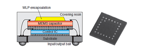
This structural difference gives MEMS capacitors several performance advantages. They typically provide higher quality factor (Q), lower insertion loss, and improved linearity, especially in microwave and millimeter-wave frequency ranges. These characteristics make them highly suitable for high-performance RF front-end systems where signal purity and low distortion are critical.
However, MEMS tunable capacitors also come with practical limitations. They are generally more expensive, have slower tuning response compared to varactor diodes, and require more complex integration processes in circuit design. In contrast, varactor diodes remain the preferred choice in most commercial RF systems because they offer fast electronic tuning, lower cost, simpler implementation, and reliable performance in VCO, PLL, and wireless communication applications.
A switched capacitor network operates on a completely different principle compared to a varactor diode. Instead of providing continuous capacitance variation, it uses multiple fixed capacitors that are selectively connected or disconnected using electronic switches such as MOSFETs. This creates discrete capacitance steps rather than smooth analog variation.
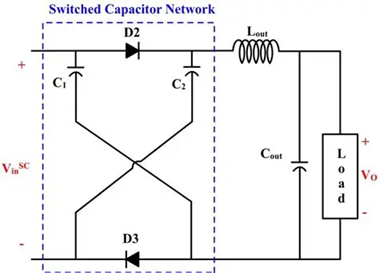
In terms of performance, switched capacitor networks offer high precision, excellent repeatability, and strong temperature stability because each capacitor has a fixed and well-defined value. They also avoid the nonlinear capacitance-voltage behavior associated with varactor diodes, making them more predictable in digital-controlled RF systems.
Despite these advantages, their main limitation is the lack of continuous tuning. Since capacitance changes in steps, frequency adjustment is less smooth, which can reduce resolution in sensitive RF applications. Varactor diodes overcome this limitation by providing continuous capacitance control through voltage variation.
Future trends in varactor diode technology focus on improving performance for next-generation high-frequency systems such as 5G, 6G, satellite communication, and radar applications. Key developments include higher Q factor, lower losses, wider tuning ranges, and better temperature stability to support operation at microwave and millimeter-wave frequencies. Research is also advancing the use of materials like GaAs and SiGe to enhance high-frequency efficiency. In addition, integration into compact RF modules and hybrid tuning systems combining varactors with MEMS and digital networks is becoming more common. These improvements ensure varactor diodes remain essential for compact, fast, and electronically controlled frequency tuning in modern communication systems.

 FPGA / CPLD
 Memory
 MOS
MOS  MCU
MCU  DSP
DSP OCEP
OCEP Secondary
  Other
Other