
075582814553

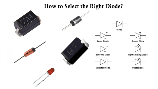
A diode is made from a semiconductor material that allows electric current to flow in only one direction. It works like a one-way gate for electricity. When the correct forward voltage is applied, the diode conducts current easily. When the voltage is reversed, it blocks the current and prevents it from flowing. This simple behavior makes diodes essential in many electronic systems such as power supplies, chargers, converters, signal protection circuits, and communication devices. In this article let’s talk about how diode selection works in practice, the key parameters that must be considered, and a step-by-step guide to selecting the right diode for different electronic applications.
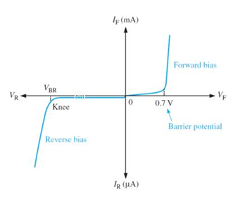
The forward voltage (VF) is the voltage drop across a diode when it is in a conducting state. This parameter directly influences power efficiency and heat generation in electronic circuits.
Typical values include:
• Silicon diodes: approximately 0.6V to 0.8V
• Schottky diodes: approximately 0.2V to 0.4V
The relationship between voltage and current is non-linear. Once the threshold is reached, the current increases exponentially rather than linearly, following the semiconductor junction characteristics.
Temperature also affects performance:
• Higher temperature reduces VF
• Lower temperature increases VF
Since power loss is determined by VF × IF, even small changes in forward voltage can significantly impact thermal behavior in high-current applications.
Current rating defines how much electrical current a diode can safely handle under specified thermal conditions. This limit is mainly determined by junction temperature and the device’s ability to dissipate heat. When the diode operates within its rated conditions, it maintains stable conduction without permanent degradation.
The maximum forward current (IF) represents the continuous current a diode can conduct under steady-state operation. This parameter is primarily limited by thermal constraints, because excessive current increases power dissipation and raises junction temperature. If this limit is exceeded for a long period, permanent damage may occur due to overheating of the semiconductor junction and package structure.
In rectifier applications, the average rectified current (IO) is used to define long-term current handling capability under AC-to-DC conversion. This value depends on waveform shape, duty cycle, and thermal design of the device. Proper heat sinking and PCB thermal management directly affect how close the diode can operate to its IO rating.
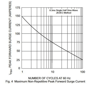
In addition to continuous operation, diodes must also withstand short-duration high-current stress. The surge current (IFSM) represents the non-repetitive peak forward current that occurs during transient events such as power-on switching or capacitor charging. Even though this condition lasts only for a few milliseconds, it can impose significant thermal and mechanical stress on the junction.
This behavior is clearly illustrated in the figure below, which shows the relationship between surge current capability and the number of AC cycles at 60 Hz. As the duration of the surge increases, the allowable peak current decreases due to accumulated thermal stress in the device.
Reverse voltage ratings define the maximum voltage a diode can block in the non-conducting state without entering breakdown. The most important parameter is Peak Repetitive Reverse Voltage (VRRM), which sets the safe operating limit during normal circuit conditions, including repetitive switching and minor voltage fluctuations.
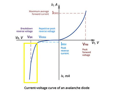
The figure illustrates the current–voltage (I–V) characteristic of an avalanche diode, showing how reverse blocking behavior is maintained up to the breakdown region. As reverse voltage increases, the diode remains in a low-leakage state until it reaches the breakdown voltage (VBR), where current rises sharply due to avalanche conduction.
In practical design, VR and VRRM must always be kept below the breakdown region with sufficient safety margin to avoid unintended conduction. Exceeding these limits forces the diode into avalanche breakdown, leading to excessive leakage current, power dissipation, and possible thermal damage.
The image clearly connects operating limits (VRRM) with the physical breakdown behavior (VBR), highlighting why proper reverse voltage selection is critical in power electronic circuits.
Switching performance describes how fast a diode transitions between conducting and non-conducting states. This behavior is mainly determined by stored charge in the PN junction during switching events.
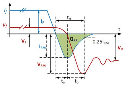
The diagram illustrates the full switching process from forward conduction to reverse blocking. When the diode switches polarity, stored charge causes a temporary reverse current known as reverse recovery current (IRM). The time required for the diode to regain its blocking state is defined as the reverse recovery time (trr).
The shaded area in the waveform represents the reverse recovery charge (Qrr), which directly corresponds to switching losses. A higher Qrr means more energy is dissipated during each switching cycle, reducing efficiency in high-frequency operation.
Junction capacitance (Cj) also affects switching behavior by influencing how quickly the diode responds to voltage changes. Lower capacitance improves switching speed, reduces losses, and enhances signal integrity in RF and fast digital circuits.
Thermal performance determines the reliability and safe operating range of a diode under load. Power dissipation is mainly calculated using VF × IF, representing the heat generated during conduction. Excessive power dissipation increases junction temperature, which reduces efficiency and shortens device lifespan.
Thermal resistance describes how effectively heat moves from the junction to the environment, with RθJC representing junction-to-case transfer and RθJA representing junction-to-ambient transfer. Lower thermal resistance improves heat flow and allows higher current operation. Maximum junction temperature (Tj max) defines the upper thermal limit beyond which permanent damage or performance degradation occurs. Derating is commonly applied in design to operate the diode below maximum ratings as temperature increases, improving long-term reliability and reducing thermal stress.
Reverse leakage current (IR) is the small current that flows when a diode is reverse biased. Silicon diodes typically exhibit very low leakage, while Schottky diodes show higher leakage due to their metal-semiconductor junction structure. Leakage current increases significantly with temperature, making it a critical parameter in precision, low-power, and high-impedance circuits. Even small leakage currents can introduce measurement errors or reduce efficiency in sensitive analog and battery-powered systems.
Energy handling capability defines how well a diode can survive transient and fault conditions. The I²t rating represents the energy a diode can withstand during short-duration surge events and is especially important in protection circuits. A higher I²t rating improves tolerance to inrush currents and short-circuit conditions. Avalanche energy (EAS) indicates the diode’s ability to safely absorb energy during controlled breakdown events, which is commonly required in surge protection and automotive electronics where voltage spikes are frequent.
Diode noise is generated due to carrier movement and switching transitions, affecting signal quality in sensitive applications. Noise performance becomes critical in RF systems, audio processing, and precision analog circuits where signal integrity must be preserved. Fast recovery diodes and Schottky diodes are often preferred because they generate lower switching noise and reduce interference, improving overall system accuracy and stability.
The physical package of a diode significantly affects thermal performance, current handling, and mechanical reliability. Larger packages typically offer better heat dissipation, while compact packages are suited for space-constrained designs but may have lower thermal capacity. PCB layout and copper area strongly influence heat distribution, making thermal design a critical factor beyond electrical specifications. The mounting method, whether surface-mount or through-hole, also impacts heat transfer efficiency and mechanical robustness under vibration or stress conditions.
Long-term diode reliability depends on electrical, thermal, and mechanical stress over time. Voltage spikes, high current surges, thermal cycling, and mechanical vibration can gradually degrade the semiconductor junction. Material aging also contributes to performance drift in long-term operation. Proper derating, stable thermal design, and controlled operating conditions significantly extend diode lifespan and maintain consistent electrical behavior throughout its service life.
In industrial and commercial systems, diodes must often comply with international safety and quality standards. Certifications such as UL, CSA, and TUV/VDE ensure that components meet strict requirements for electrical safety, reliability, and environmental durability. Compliance with these standards is essential in regulated industries, where consistent performance and failure prevention are critical for system safety and certification approval.
• Power supply diode overheating in operation - A diode works normally at light load but overheats under full load because real operating current is higher than expected, leading to thermal failure.
• SMPS failure due to slow recovery diode - A standard rectifier diode is used in a switching power supply, causing excessive switching loss, heat buildup, and reduced efficiency at high frequency.
• Voltage breakdown during surge events - In power input circuits, voltage spikes during startup or load switching exceed diode rating, resulting in sudden short-circuit or permanent breakdown.
• Unexpected efficiency loss in low-voltage designs - In 5V or 12V systems, a diode with high forward voltage causes significant power loss, reducing overall system efficiency.
• Reverse leakage affecting battery-powered devices - In standby or sleep mode circuits, small leakage current slowly drains the battery, reducing standby time.
• EMI issues in high-speed switching circuits - A diode with high reverse recovery charge generates switching noise, causing electromagnetic interference in nearby signal lines.
• Sensor signal distortion in precision circuits - Junction capacitance of the diode alters signal behavior in analog or RF paths, resulting in inaccurate measurements.
• Thermal failure in compact PCB layouts - A diode performs well in testing but fails in real product due to insufficient PCB copper area and poor heat dissipation.
• Surge damage in power-on conditions- During capacitor charging at startup, inrush current exceeds diode capability, causing sudden failure even if normal current is within limits.
• Automotive circuit failure under temperature extremes - A diode that works at room temperature fails in hot environments due to reduced thermal margin and accelerated leakage current.
Start by identifying the maximum voltage present in the circuit, including normal operation and transient spikes.
• Determine the peak reverse voltage in the application
• Select a diode with VRRM higher than the maximum circuit voltage
• Add a safety margin (typically 20%–50%) for unexpected surges
This prevents reverse breakdown and ensures stable operation under voltage stress.
Next, calculate the expected current flowing through the diode during operation.
• Identify continuous forward current (IF)
• Check average rectified current (IO) for AC applications
• Consider peak surge current (IFSM) during startup conditions
Choose a diode that can safely handle both continuous and transient current levels.
Diode performance is strongly influenced by heat generation.
• Estimate conduction loss using: P = VF × IF
• Check thermal resistance (RθJA / RθJC)
• Ensure junction temperature stays below maximum limit (Tj max)
If heat dissipation is insufficient, the diode may fail even if electrical ratings are within limits.
For switching or high-frequency circuits, diode speed is critical.
• Use fast recovery diodes or Schottky diodes for high-speed applications
• Check reverse recovery time (trr)
• Consider reverse recovery charge (Qrr) for switching efficiency
Slower diodes increase switching losses and reduce system efficiency.
In RF or fast digital systems, parasitic effects become important.
• Check junction capacitance (Cj)
• Lower capacitance improves signal integrity
• High Cj may cause distortion or EMI issues
This step is essential for communication and precision signal circuits.
Leakage current affects low-power and precision applications.
• Silicon diodes: very low leakage
• Schottky diodes: higher leakage, especially at high temperature
• Evaluate impact in standby or battery-powered systems
Choose a diode with acceptable leakage behavior for the circuit type.
Real-world circuits often experience short pulses and fault conditions.
• Check surge current rating (IFSM)
• Consider I²t rating for energy absorption capability
• Evaluate avalanche energy rating (EAS) if applicable
This ensures protection against inrush current and transient events.
Physical construction affects thermal and electrical performance.
• SMD packages offer compact design but lower thermal capacity
• Through-hole packages handle higher power more effectively
• PCB copper area plays a major role in heat dissipation
The package must match both electrical and thermal requirements.
Finally, ensure the diode can operate under real-world conditions.
• Temperature cycling and thermal stress
• Mechanical durability
• Long-term aging behavior
• Operating environment (industrial, automotive, consumer)
Select the correct diode category based on application needs:
• Schottky diode → high efficiency, low voltage drop, fast switching
• Fast recovery diode → switching power supplies and converters
• Standard rectifier diode → low-frequency AC rectification
• Protection diode → surge and transient suppression
Selecting the right diode requires a complete understanding of electrical, thermal, and dynamic behavior under real operating conditions. In practical designs, correct diode selection improves efficiency, reduces heat generation, prevents breakdown during voltage spikes, and ensures stable operation over time. On the other hand, incorrect selection can lead to energy loss, unstable switching behavior, or premature component failure, especially in high-frequency or high-power systems.

 FPGA / CPLD
 Memory
 MOS
MOS  MCU
MCU  DSP
DSP OCEP
OCEP Secondary
  Other
Other