
075582814553

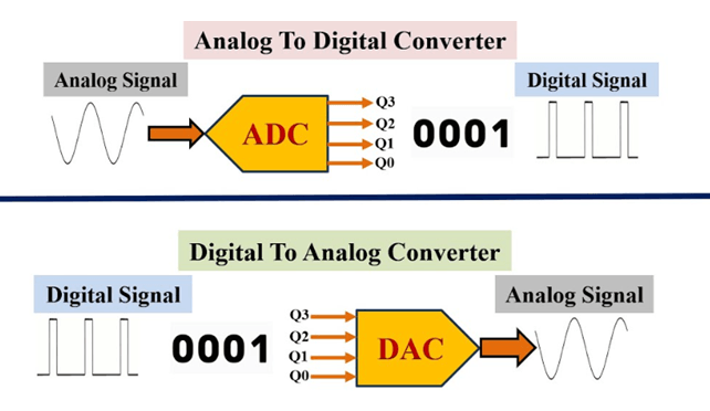
Analog-to-digital converters (ADC) and digital-to-analog converters (DAC) act as a bridge between the analog world, where real signals such as sound, temperature, and voltage exist, and the digital world, where information is processed and stored. This article explains the most important ADC and DAC terminology used in real circuits. Each term plays a role in how a converter handles real-world signals, especially in applications like communication systems, audio processing, sensors, and industrial electronics.
Acquisition time is the period required for the ADC’s internal sampling capacitor to charge and settle to the input voltage after switching from track to hold mode. In practical ADC design, this is not just a delay—it determines whether the sampled value is accurate or distorted.
It matters because if the input signal changes faster than the acquisition time allows, the capacitor will not fully settle, producing conversion errors. In high-speed data acquisition systems such as motor control or RF sampling, insufficient acquisition time leads to waveform distortion and incorrect digital representation. Designers must match acquisition time with input source impedance and sampling rate to maintain accuracy.
Aliasing is a sampling error that occurs when a signal is sampled below the Nyquist rate. High-frequency components are “folded” into lower frequencies, creating false signals that were not actually present in the input.
This is critical in real systems because aliasing cannot be corrected after conversion. For example, in audio systems it produces unwanted tones, while in sensor systems it creates misleading measurements. Anti-aliasing filters are therefore required before the ADC to remove frequencies above half the sampling rate.
Aperture delay is the time difference between the sampling clock edge and the exact instant the ADC captures the input signal.
In real circuits, this delay becomes important when measuring fast-changing signals. Even small delays can cause phase errors between channels in multi-channel systems, leading to inaccurate timing analysis in applications such as oscilloscopes or communication receivers.
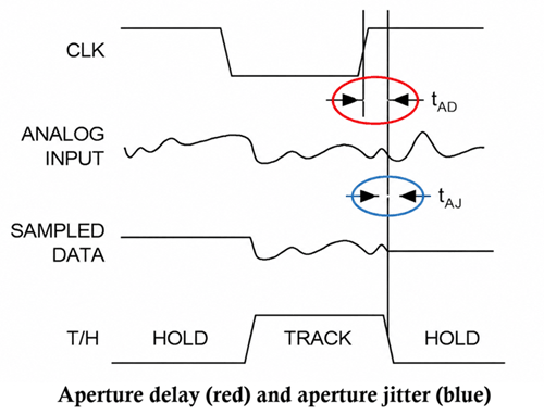
Aperture jitter refers to random variations in the sampling instant. Unlike fixed delay, jitter introduces uncertainty in when sampling occurs.
It is especially critical at high input frequencies because timing uncertainty translates directly into voltage noise. In RF and high-speed ADCs, aperture jitter can significantly degrade SNR, limiting achievable resolution even if the ADC has high bit depth.
Binary encoding in unipolar ADCs maps only positive input voltages into digital values, typically from 0 to full-scale.
It is widely used in single-supply systems such as battery-powered sensors. The limitation is that negative signals cannot be represented directly, requiring level shifting or biasing.
A bipolar input allows signals to swing above and below a reference level (often ground or mid-supply). This is essential in differential systems such as audio, instrumentation amplifiers, and industrial sensors because it preserves both positive and negative waveform information without distortion or clipping.
Common Mode Rejection describes how well a differential system ignores identical signals appearing on both inputs. In real ADC systems, high CMR is important because noise often enters both signal lines equally (e.g., EMI). A high CMR ratio ensures only the differential signal is converted, improving accuracy in noisy industrial environments.
Crosstalk is unwanted signal coupling between adjacent channels in multi-channel ADC/DAC systems. It matters in dense PCB layouts where high-frequency signals can interfere with neighboring channels. This reduces measurement accuracy in systems like multi-sensor arrays, audio mixers, and communication base stations.
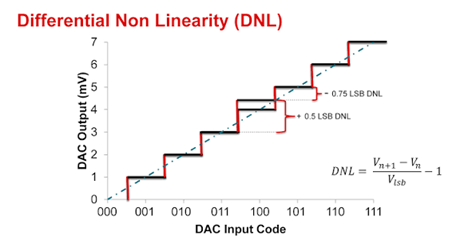
DNL measures how much each ADC step deviates from the ideal 1 LSB increment. In practical terms, it determines whether the ADC output transitions smoothly or has missing codes. High DNL causes uneven resolution and can create distortion in precision measurement systems such as digital instrumentation
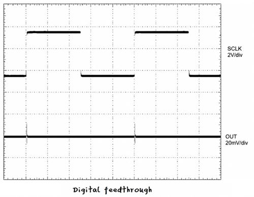
Digital feedthrough is noise appearing at the DAC output due to internal digital switching. It is important in mixed-signal systems because fast digital transitions can couple into the analog output, creating spikes that reduce signal purity, especially in audio and waveform generation systems.
Dynamic range is the ratio between the smallest detectable signal and the largest undistorted signal. A higher dynamic range allows a system to measure weak signals in the presence of strong signals, which is critical in radar, medical imaging, and audio processing.
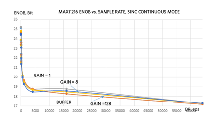
ENOB represents the real usable resolution of an ADC after accounting for noise and distortion. Even if an ADC is rated at 12 or 16 bits, real ENOB is often lower due to thermal noise, jitter, and nonlinearity. This makes ENOB a more practical performance indicator than nominal resolution.
RMS (Root Mean Square) is the equivalent DC value of an AC signal that represents its power content. It is used in ADC/DAC systems to evaluate signal strength in power electronics, audio, and sensor systems.
This defines the maximum input frequency where the ADC can still process a full-scale signal without significant attenuation. Crucial in high-frequency applications because even if sampling rate is high, analog front-end limitations can reduce usable bandwidth.
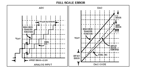
Full-scale error is the deviation between actual output and ideal maximum output. Directly affects calibration accuracy in measurement systems and must be corrected in precision ADC applications.
This is the scaling error across the entire transfer function range. Affects how accurately input voltage maps to digital output and is often corrected using calibration coefficients.
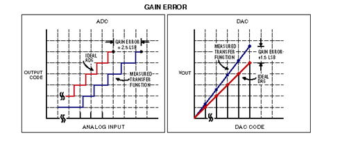
Gain error measures deviation in slope between actual and ideal transfer function. In real systems, it leads to proportional measurement inaccuracies across all input levels.
Gain error drift describes how gain changes with temperature. Critical in industrial environments where temperature variation can lead to long-term measurement instability.
Gain consistency ensures multiple ADC channels produce identical amplification behavior. It is essential in multi-channel systems such as phased arrays and multi-sensor measurement platforms.
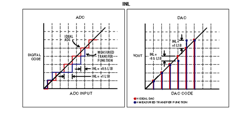
INL measures how far the ADC transfer function deviates from an ideal straight line after removing offset and gain errors. Directly affects accuracy and linearity, making it one of the most important specifications in precision ADCs.
IMD occurs when multiple signals mix due to nonlinear behavior, producing unwanted frequency components.
LSB is the smallest voltage change that corresponds to a one-step change in digital output. Defines resolution granularity and determines how finely an ADC can distinguish small signal variations.
Load sensing measures voltage or current directly at the load rather than at the source. This improves regulation accuracy in power systems by compensating for voltage drops across wiring.
The most critical switching event in a DAC where the most significant bit changes state, often causing output glitches.
The highest weighted bit in a binary number, responsible for the largest contribution to output value.
A DAC that uses an external analog reference signal, allowing it to scale AC signals digitally.
The highest frequency that can be accurately sampled without aliasing, equal to half the sampling rate.
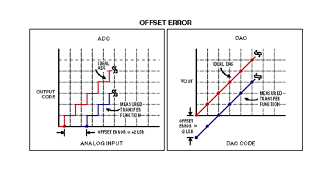
Offset error represents deviation at zero input level compared to ideal output behavior.
Temperature-induced variation in offset error over time.
Sampling at a rate significantly higher than the Nyquist frequency to improve resolution and reduce noise.
The degree of timing alignment between multiple ADC channels measuring the same signal.
The ability of a converter to suppress output variation caused by changes in supply voltage.
The difference between actual analog input and its nearest digital representation.
A measurement technique where reference voltage is proportional to input signal, improving accuracy in variable systems.
The number of bits used to represent analog signals digitally. Higher resolution improves accuracy.
The number of samples captured per second by an ADC.
The ratio of signal power to noise power in a system.
A performance metric that includes both noise and distortion relative to the main signal.
The maximum rate at which output voltage can change over time.
The frequency range where the converter operates linearly with low amplitude signals.
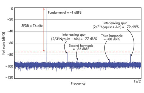
The difference between the main signal and the largest unwanted spectral component.
Spike or glitch energy is unwanted transient output during DAC switching. It affects waveform accuracy in precision analog output systems.
This circuit samples an analog signal and holds it steady during conversion. ADCs require stable input during the conversion process.
Transition noise is uncertainty when ADC output switches between adjacent codes. Determines how stable digital output appears near threshold boundaries.
THD measures harmonic content generated by nonlinear distortion.
Under-sampling intentionally samples below Nyquist for high-frequency signal analysis. Used in RF systems with band-pass signals.
Unipolar input refers to signals that only vary in one polarity range. Simplifies ADC design but limits signal representation flexibility.
This is another form of offset error in unipolar systems, representing deviation at zero input. Mainly affects low-level signal accuracy.
• Resolution vs Accuracy Confusion - Resolution refers to the number of bits in a converter, while accuracy refers to how close the output is to the true analog value. High resolution does not automatically guarantee high accuracy because noise, gain error, offset error, and nonlinearity still affect performance.
• SNR, SINAD, and THD Misinterpretation - Signal-to-Noise Ratio (SNR) considers only noise, while SINAD includes both noise and distortion. Total Harmonic Distortion (THD) measures only harmonic distortion. Treating these as identical leads to incorrect evaluation of signal quality.
• ENOB vs ADC Bit Resolution - Effective Number of Bits (ENOB) represents real-world usable resolution under noise and distortion conditions, while ADC bit resolution is the theoretical maximum. Assuming both are equal can result in incorrect system performance expectations.
• Sampling Rate vs Bandwidth - Sampling rate defines how often samples are taken, while bandwidth defines the range of frequencies that can be accurately processed. Ignoring the Nyquist requirement can lead to aliasing and signal distortion.
• INL vs DNL Error - Differential Nonlinearity (DNL) affects step size uniformity between adjacent codes, while Integral Nonlinearity (INL) measures overall deviation from the ideal transfer curve. Treating them as the same can lead to incorrect linearity evaluation.
• Ignoring the Impact of Real-World Noise and Distortion - Many users assume ideal converter behavior, but real ADCs and DACs are affected by thermal noise, quantization noise, jitter, and nonlinear distortion, which significantly impact performance.
• Ideal vs Practical Performance - Datasheet values often represent ideal or test-specific conditions. In real applications, performance varies depending on temperature, frequency, load conditions, and circuit design.
The terms mentioned above define how accurately a system can capture, convert, and reproduce signals under real operating conditions. Mastering ADC and DAC terminology directly improves engineering accuracy, system stability, and design efficiency. It also allows engineers to evaluate components more critically, optimize signal integrity, and ensure that real-world performance matches design expectations.

 FPGA / CPLD
 Memory
 MOS
MOS  MCU
MCU  DSP
DSP OCEP
OCEP Secondary
  Other
Other