
075582814553

In digital electronics, undefined or “floating” input states can cause erratic behavior, signal noise, and unnecessary power consumption. To solve this, you can rely on pull-up and pull-down resistors, simple but active components that ensure input pins default to a known logic level when not actively driven. This article examines how these resistors function, how to select the appropriate values, and best practices for integrating them into applications such as switches, microcontrollers, and communication protocols.
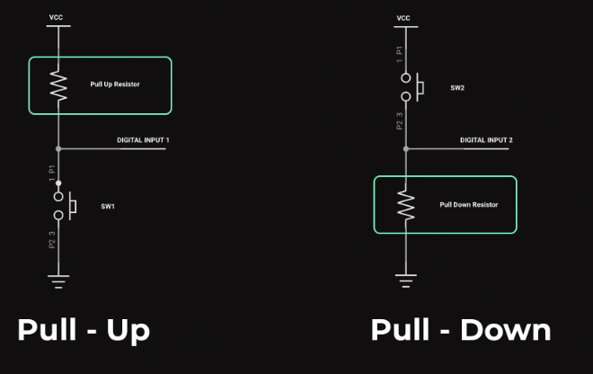
Figure 1. Pull-Up and Pull-Down Resistors
Pull-up and pull-down resistors are basic passive components used in digital circuits to ensure input pins settle at a known logic level when no active signal is present. Without these resistors, high-impedance inputs on microcontrollers, logic gates, and ICs can “float,” picking up electrical noise and causing erratic behavior, false triggering, or increased power consumption.
• Pull-up resistor: Connects the input pin to the positive voltage supply (VCC), setting the default logic level to HIGH (e.g., 3.3V or 5V).
• Pull-down resistor: Connects the input pin to ground (GND), forcing the default logic level to LOW (0V).
Pull-up and pull-down resistors are typically used in circuits where an input pin needs to have a default state but must also respond to external signals, such as switches, sensors, or digital communication lines (like I²C or UART). Their function is to safely bias the input to a known voltage level, HIGH or LOW, when no active signal is present.
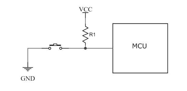
Figure 2. Pull-Up Resistor Configuration
In a pull-up configuration, the resistor connects between the input pin and the positive voltage rail (VCC). A switch or external device is then connected between the input and ground (GND).
• Switch open: When the switch is not pressed or the external circuit is inactive, the pull-up resistor gently pulls the input pin up to VCC, resulting in a logic HIGH state.
• Switch closed: Pressing the switch or activating the external signal connects the input directly to ground, overriding the resistor and driving the input LOW.
This configuration is common in button circuits, where the input should remain HIGH unless a button is pressed to ground it.
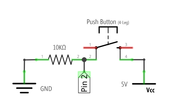
Figure 3. Pull-Down Resistor Configuration
In contrast, a pull-down resistor connects the input pin to ground. The switch or external device is then placed between the input and VCC.
• Switch open: With no signal from the switch, the pull-down resistor keeps the input at ground potential, resulting in a logic LOW.
• Switch closed: Activating the switch connects the input to VCC, overriding the resistor and driving the input HIGH.
This setup is useful in circuits where an input should default to LOW unless an external source explicitly drives it HIGH.
| Feature | Pull-Up Resistor | Pull-Down Resistor |
| Connected To | Positive supply voltage (VCC) | Ground (GND) |
| Default Logic Level | Logic HIGH (e.g., 3.3V or 5V) | Logic LOW (0V) |
| Common Use Cases | I²C communication lines, open-drain outputs, and GPIOs needing a HIGH idle state | GPIO inputs needing a LOW idle state, specific logic control scenarios |
| Switch Open State | Input reads HIGH | Input reads LOW |
| Switch Closed State | Input is pulled to LOW (via ground) | Input is pulled to HIGH (via VCC) |
In digital circuit design, the resistor must be strong enough to keep the line at a known state, but not so strong that it blocks intended signal overrides. The value chosen impacts three critical performance areas:
• power consumption
• signal speed
• noise immunity
High resistance (10kΩ – 100kΩ) is preferred for reducing current draw. These values are ideal for battery-powered or low-power embedded systems. They perform well in low-speed signals where timing is not critical and transitions are infrequent. However, the drawback is that weak pull strength increases noise susceptibility, which may cause signal lines to float or behave erratically in noisy environments.
Low resistance (1kΩ – 5kΩ) offers faster signal transitions, making it suitable for high-speed digital circuits. It also improves noise immunity by providing stronger pull strength, enhancing signal integrity. The trade-off is higher power consumption, especially when the line is pulled to the opposite logic state. This could be a concern in energy-sensitive designs.
| System Type | Typical Pull Resistor Range |
| 5V TTL logic | 1 kΩ – 5 kΩ |
| 3.3V CMOS logic | 10 kΩ – 50 kΩ |
| Open-drain lines (e.g., I²C) | 2.2 kΩ – 10 kΩ (depending on bus speed and capacitance) |
To calculate the resistor value, use the basic formula from Ohm’s Law:
Where:
• R = Resistance (in ohms, Ω)
• V = Supply voltage (typically 3.3 V or 5 V in digital circuits)
• I = Desired current through the resistor (in amperes, A)
This current is usually selected based on how much "pull strength" is needed to maintain a defined logic level without drawing excessive power.
• Goal: Select a pull-up resistor for a 5V digital input, allowing approximately 0.5 mA of current.
In this case, a 10 kΩ resistor will pull the line up to 5 V with a 0.5 mA current when the input is idle. This value provides a good balance between low power draw and adequate noise immunity.
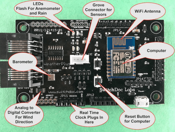
Figure 4. GPIO (General-Purpose Input and Output) Inputs
When configuring microcontroller pins as inputs, it’s important to prevent them from floating if no signal source is connected. Pull-up or pull-down resistors ensure a default logic level, avoiding unpredictable behavior or power-wasting oscillations. Many microcontrollers offer internal pull-ups, but external resistors are often used for added control or when internal options are unavailable.
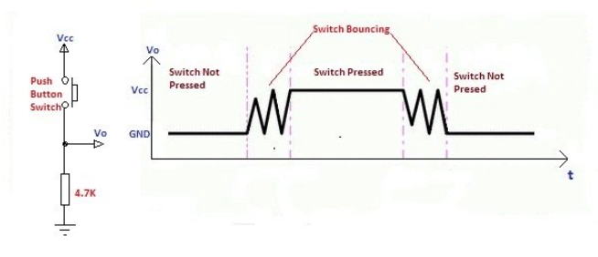
Figure 5. Switch Debouncing
Mechanical switches naturally bounce when pressed or released, causing multiple rapid transitions between HIGH and LOW. A pull-up or pull-down resistor, in combination with software or hardware debouncing techniques, helps stabilize the input signal, ensuring the microcontroller registers only a single clean transition per press.
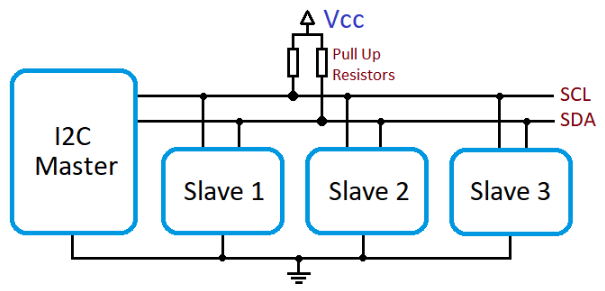
Figure 6. I²C Communication (Inter-Integrated Circuit)
In I²C protocols, both the SCL (clock) and SDA (data) lines use open-drain or open-collector configurations. This means that devices can only pull the line LOW and must rely on external pull-up resistors to bring the line HIGH when no device is actively driving it. Without pull-up resistors, I²C communication cannot function correctly, as the lines would remain undefined or stuck LOW.
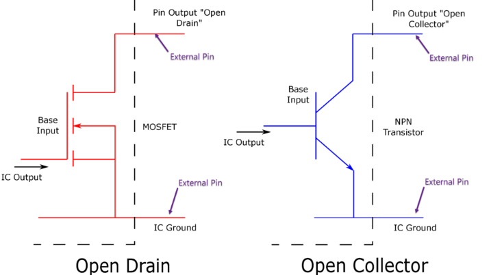
Figure 7. Open-Drain or Open-Collector Outputs
Some digital outputs, like those from transistors, sensors, or logic ICs, are designed to only sink current (pull the line LOW) and require a pull-up resistor to establish a HIGH level when inactive. These are common in bus systems, interrupt lines, and wired-AND logic configurations.
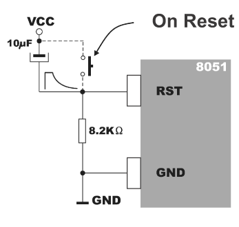
Figure 8. Reset and Interrupt Lines
In many microcontroller-based systems, reset pins or external interrupt lines use pull-up resistors to maintain a default HIGH state. When pulled LOW by a button press or external circuit, these lines trigger a system reset or interrupt event. Without the resistor, the input might float, causing false triggers or system instability.
• Ensure stable logic levels: These resistors prevent floating inputs by holding a pin at a known voltage level (HIGH or LOW) when no active signal is applied. This eliminates erratic or undefined digital states.
• Inexpensive and easy to implement: Pull resistors are basic passive components, typically costing only a few cents. Their simple implementation makes them an ideal choice for circuit stabilization in professional designs.
• Often built-in on microcontroller pins: Many modern microcontrollers (e.g., Arduino, STM32, ESP32, and AVR chips) offer configurable internal pull-up or pull-down resistors, which simplifies circuit design by reducing the need for external components.
• Useful for protocols like I²C and SPI: Open-drain communication standards rely on pull-up resistors for proper operation, making them requisite in multi-device communication setups.
• Draw static current when overridden: When the input is actively driven opposite to the pull resistor (e.g., pulling LOW against a pull-up), a small amount of static current flows through the resistor. This contributes to power loss, especially in low-power or battery-operated devices.
• Can slow signal transitions if the resistance is too high: High resistance values limit the current available to charge or discharge any stray capacitance on the line. This can result in slower rise or fall times, affecting the performance of high-speed signals or timing-sensitive applications.
• Improper values may cause noise sensitivity: If the resistor value is too high, the input may become susceptible to electromagnetic interference (EMI) or ambient noise, leading to false logic transitions and unstable behavior.
Pull-up and pull-down resistors may be small in size, but their role in digital circuit stability is significant. From preventing floating inputs to enabling reliable communication protocols, they offer a straightforward yet powerful solution for maintaining predictable logic states. By understanding their configurations, selecting appropriate values, and applying best practices, you can improve noise immunity, reduce power consumption, and enhance overall circuit reliability.

 FPGA / CPLD
 Memory
 MOS
MOS  MCU
MCU  DSP
DSP OCEP
OCEP Secondary
  Other
Other