
075582814553

Inductors are important components in power supplies, filters, RF circuits, and communication systems. However, real inductors are not ideal because they have resistance, losses, and parasitic effects that can affect circuit performance. This article will discuss what inductor Q-factor means, why it is important, how it affects performance, and how to choose the right inductor based on Q-factor.
The Quality Factor (Q-Factor) of an inductor is a measure of how efficiently the inductor stores magnetic energy compared to the energy it loses during operation. It is one of the most important parameters used to evaluate inductor performance, especially in RF circuits, resonant networks, filters, oscillators, and impedance-matching applications.
An ideal inductor stores energy without any loss. In practice, every inductor contains winding resistance, magnetic core losses, and parasitic effects that convert part of the stored energy into heat. The Q-factor helps quantify these losses.
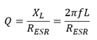
The Q-factor is defined as the ratio of inductive reactance to effective series resistance at a given frequency.
Where:
• Q = Quality factor
• XL = Inductive reactance
• f = Operating frequency
• L = Inductance
• RESR = Effective series resistance
This equation shows that Q-factor increases when inductive reactance is large and decreases when losses become significant.
Consider an inductor with:
• Inductance (L) = 10 µH
• Frequency (f) = 10 MHz
• ESR = 2 Ω
First calculate the inductive reactance:
XL=2πfL
XL=2π(10×106)(10×10-6)
XL≈628 Ω
Then calculate the Q-factor:
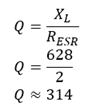
This indicates a very high-Q inductor suitable for RF and resonant applications.
Many inductors may have the same inductance value but perform very differently in actual circuits. The Q-factor helps you evaluate the efficiency and loss characteristics of an inductor at a specific operating frequency. Q-factor helps compare the loss characteristics of inductors operating at the same frequency. For this reason, Q-factor is often considered alongside inductance, current rating, DC resistance, and self-resonant frequency when selecting an inductor.
Several loss mechanisms reduce the Q-factor of a practical inductor.
The copper wire used to form the winding has a finite resistance known as DC Resistance (DCR). When current flows through the winding, power is dissipated as heat.
The DCR depends on:
• Wire diameter
• Wire length
• Number of turns
• Conductor material
Generally, larger wire diameters produce lower resistance and improve efficiency.
| AWG | mΩ/ft | mΩ/m | AWG | mΩ/ft | mΩ/m | AWG | mΩ/ft | mΩ/m | AWG | mΩ/ft | mΩ/m |
| 0 | 0.1 | 0.32 | 10 | 1 | 3.2 | 20 | 10 | 32 | 30 | 100 | 320 |
| 1 | 0.125 | 0.4 | 11 | 1.25 | 4 | 21 | 12.5 | 40 | 31 | 125 | 400 |
| 2 | 0.16 | 0.5 | 12 | 1.6 | 5 | 22 | 16 | 50 | 32 | 160 | 500 |
| 3 | 0.2 | 0.64 | 13 | 2 | 6.4 | 23 | 20 | 64 | 33 | 200 | 640 |
| 4 | 0.25 | 0.8 | 14 | 2.5 | 8 | 24 | 25 | 80 | 34 | 250 | 800 |
| 5 | 0.32 | 1 | 15 | 3.2 | 10 | 25 | 32 | 100 | 35 | 320 | 1000 |
| 6 | 0.4 | 1.25 | 16 | 4 | 12.5 | 26 | 40 | 125 | 36 | 400 | 1250 |
| 7 | 0.5 | 1.6 | 17 | 5 | 16 | 27 | 50 | 160 | 37 | 500 | 1600 |
| 8 | 0.64 | 2 | 18 | 6.4 | 20 | 28 | 64 | 200 | 38 | 640 | 2000 |
| 9 | 0.8 | 2.5 | 19 | 8 | 25 | 29 | 80 | 250 | 39 | 800 | 2500 |
Table: Approximate Resistance of Copper Wire can be used to compare the resistance of different AWG wire sizes. Thicker conductors have lower resistance and typically contribute to a higher Q-factor.
As frequency increases, current no longer distributes evenly throughout the conductor.
Instead, current becomes concentrated near the conductor surface. This phenomenon is known as the skin effect. The reduced effective conductor area increases AC resistance and causes additional power loss.
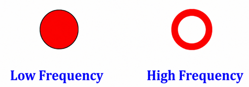
Current Flow Area in a Conductor Coil
The figure illustrates how current occupies nearly the entire conductor cross-section at low frequencies, while at higher frequencies it becomes confined to a thin outer layer. This reduction in usable conductor area increases resistance and lowers the Q-factor.
In practical inductors, conductors are closely spaced together. The magnetic fields generated by neighboring turns force current to crowd into specific regions of the wire.
This phenomenon is called the proximity effect.
At high frequencies, proximity effect can increase AC resistance significantly and may contribute more loss than skin effect alone, especially in multilayer windings and high-current inductors.
Inductors that use magnetic cores experience additional losses within the core material.
Core losses consist mainly of:
• Hysteresis loss
• Eddy current loss
These losses increase with operating frequency and magnetic flux density.
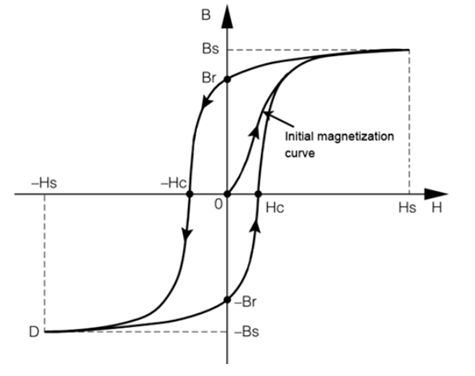
B-H Curve of Soft Ferrite
The B-H curve illustrates the magnetic behavior of ferrite materials. The enclosed area of the hysteresis loop represents energy lost during each magnetization cycle. Larger loop areas correspond to greater hysteresis losses and lower Q-factor performance.
Adjacent winding turns are separated by insulation, creating small unintended capacitors throughout the coil structure.
This effect is known as interwinding capacitance or parasitic capacitance.
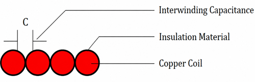
Interwinding Capacitance Between Coil Turns
The figure shows how insulation between neighboring turns forms distributed capacitance. Although this capacitance does not directly create resistive loss, it affects high-frequency performance and contributes to the inductor's self-resonant frequency (SRF).
The Q-factor can also be expressed as the ratio between stored energy and dissipated energy during each cycle.
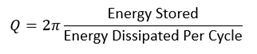
This definition provides a physical interpretation of Q-factor.
• High-Q inductors store much more energy than they lose.
• Low-Q inductors dissipate a larger percentage of stored energy as heat.
The Q-factor does not remain constant over frequency.
Typically:
• Q-factor increases initially as inductive reactance rises.
• A peak Q value is reached at a specific frequency.
• Q-factor decreases at higher frequencies as AC resistance, core losses, and parasitic effects become dominant.
For this reason, manufacturers usually specify Q-factor at a particular test frequency rather than providing a single value for all operating conditions.
The Q-factor varies significantly depending on the inductor construction, core material, and operating frequency.
| Inductor Type | Typical Q Range |
| Power Inductors | 5–50 |
| Ferrite-Core Inductors | 20–150 |
| Air-Core RF Inductors | 50–300+ |
| High-Frequency RF Inductors | 100–500+ |
| Chip Inductors (SMD) | 10–100 |
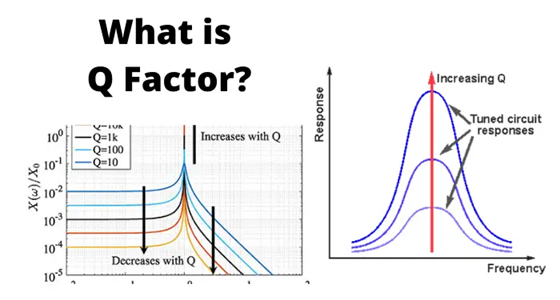
The quality factor, or Q factor, has a direct effect on how an inductor performs in a circuit. It is especially important in filters, resonant circuits, RF systems, oscillators, and communication equipment where frequency control matters.
In simple terms, the Q factor shows how selective and efficient an inductor is at a certain frequency. A higher Q value means the inductor has lower losses and can create a sharper frequency response. A lower Q value means the inductor has higher losses and produces a wider, less selective response.
In filter circuits, the Q factor strongly affects bandwidth. Bandwidth is the range of frequencies that a filter allows to pass through.
A high-Q inductor creates a narrow bandwidth. This is useful when a circuit must select one specific frequency and reject nearby unwanted signals. This type of response is common in RF filters, radio receivers, wireless communication systems, and tuned circuits.
A low-Q inductor creates a wider bandwidth. This can be useful when the circuit needs to pass a broader range of frequencies, but it also provides less selectivity.
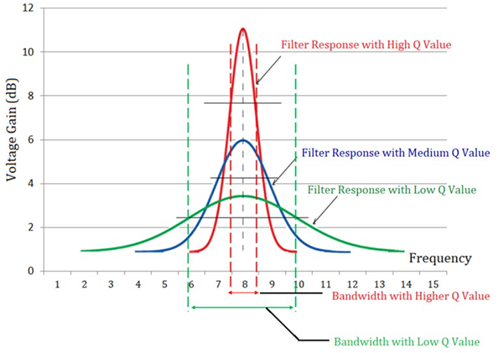
Filter Response at Different Q Values image shows how Q factor changes the shape of a filter response.
The red curve represents a high Q value. It has the highest peak gain and the narrowest bandwidth. This means the filter is very selective and mainly passes signals near the center frequency.
The blue curve represents a medium Q value. It provides a balanced response, with moderate gain and moderate bandwidth.
The green curve represents a low Q value. It has a lower peak and a wider bandwidth. This means the filter allows a wider range of frequencies to pass, but it is less effective at selecting one exact frequency.
| Comparison Point | High-Q Inductor | Low-Q Inductor |
| Typical Q factor range | Usually above 50; RF types may reach 100–300+ | Usually below 20; often around 5–20 |
| Main behavior | Stores energy efficiently with low loss | Has higher loss and wider response |
| Equivalent series resistance | Low ESR | Higher ESR |
| Power loss | Lower power loss | Higher power loss |
| Heat generation | Lower heating | More heating |
| Bandwidth | Narrow bandwidth | Wide bandwidth |
| Frequency selectivity | Very good; separates close frequencies better | Lower; passes a wider frequency range |
| Resonant peak | Sharp and high peak | Broad and lower peak |
| Filter performance | Best for narrowband and tuned filters | Better for broadband or non-selective filtering |
| Signal rejection outside passband | Stronger attenuation of unwanted signals | Weaker attenuation of unwanted signals |
| Efficiency | High efficiency at the designed frequency | Lower efficiency because more energy is lost |
| Frequency sensitivity | More sensitive to tolerance, layout, and frequency shift | Less sensitive to exact tuning |
| Advantage | Low loss, high selectivity, strong resonant gain, better RF performance | Wider bandwidth, simpler design, often lower cost, useful in power circuits |
| Disadvantage | Narrow bandwidth, higher cost, needs careful layout, not ideal for broadband circuits | Higher loss, lower gain, poorer selectivity, more heat |
| Typical applications | RF filters, band-pass filters, oscillators, antenna matching, radio receivers, tuned circuits, wireless systems | DC-DC converters, power supply chokes, EMI filters, broadband circuits, energy storage inductors |
| Best used when | The circuit needs sharp tuning, low loss, and narrowband frequency control | The circuit needs wider bandwidth, power handling, or general filtering |
Every practical inductor contains parasitic capacitance between its winding turns. Together with the inductance, this capacitance creates a natural resonant frequency known as the Self-Resonant Frequency (SRF).
As the operating frequency approaches the SRF, the Q-factor typically reaches its maximum value and then begins to decline rapidly. Above the self-resonant frequency, the component behaves more like a capacitor than an inductor.
For reliable circuit operation, you should select an inductor whose SRF is significantly higher than the intended operating frequency.
Several design techniques can improve the Q-factor of an inductor:
- Use thicker conductors to reduce DC resistance.
- Use low-loss core materials.
- Reduce the number of winding layers.
- Minimize proximity-effect losses.
- Use litz wire in high-frequency applications.
- Operate well below the self-resonant frequency.
- Select inductors with low ESR specifications.
Improving Q-factor can increase efficiency, reduce heating, and enhance overall circuit performance.
High-Q inductors are commonly used in RF filters for wireless communication systems. These filters help separate the desired signal from nearby unwanted frequencies while keeping signal loss low. They are useful in mobile networks, radio transmitters, satellite systems, GPS receivers, and wireless data links.
Oscillator circuits use inductors and capacitors to generate stable repeating signals. A high-Q inductor helps reduce losses in the resonant circuit, which supports better frequency stability, cleaner waveforms, and lower phase noise. This is important in signal generators, frequency synthesizers, transmitters, and timing circuits.
High-Q inductors are used in antenna matching networks to improve power transfer between the transmitter and antenna. Because they have lower losses, more RF power reaches the antenna instead of being wasted as heat. This can improve transmission efficiency and help support better wireless range.
High-Q inductors are also used in resonant tank circuits where low losses help maintain strong resonance and stable circuit operation.
Many test instruments need accurate signal generation and frequency analysis. High-Q inductors help reduce internal circuit losses, which supports better stability and measurement accuracy in equipment such as spectrum analyzers, signal generators, impedance analyzers, and network analyzers.
Aerospace and defense systems often operate in demanding high-frequency environments. High-Q inductors help improve signal sensitivity and reduce unwanted frequency interference in radar, navigation, and military communication systems.
Medical and scientific instruments often require clean high-frequency signals and stable measurement performance. High-Q inductors help reduce signal loss and noise in systems such as medical imaging equipment, RF sensors, and laboratory measurement devices.
Understanding Q-factor helps you choose the right inductor for a circuit instead of looking only at inductance value. Two inductors may have the same inductance, but they can perform very differently at high frequencies. By knowing how Q-factor works, you can better understand why some inductors are better for sharp frequency selection, lower power loss, and stable circuit performance.

 FPGA / CPLD
 Memory
 MOS
MOS  MCU
MCU  DSP
DSP OCEP
OCEP Secondary
  Other
Other