What Is an Oscilloscope
FREE-SKY (HK) ELECTRONICS CO.,LIMITED / 06-12 16:54
Delving into the intricate realm of electronics tests and measurement necessitates a mention of the oscilloscope. This device artfully translates the enigmatic language of electrical signals into intuitive waveform diagrams. It's a window, a portal really, through which engineers and scientists gain insights into the electronic world’s hidden dynamics. Oscilloscopes, evolving significantly since Ferdinand Braun's pioneering work in the late 19th century, have journeyed a long and fruitful path.
Catalog
1. Definition and History of Oscilloscope
2. Oscilloscope Classification
3. Application Scenarios of Oscilloscopes
4. Oscilloscope User Group
5. Working Principle of Oscilloscope
6. Oscilloscope Measurement Capabilities
7. How to Use Oscilloscope
8. Oscilloscope Performance Optimization
9. Oscilloscope Selection Factors
10. Oscilloscope Final Selection Guide
11. Summary
Initially, we saw the cathode ray tube experiments, a rudimentary yet revolutionary beginning. Now, the landscape is dominated by the advanced digital storage oscilloscope (DSO). Each leap in this instrument's technology echoes the strides in electronic engineering and technological innovation.
The evolution of oscilloscopes is nothing short of remarkable. From basic signal display, they have expanded into realms of complex signal analysis and processing. This journey has cemented their role as pivotal in the design, testing, fault diagnosis, and education and training of electronic equipment. Essentially, they are fundamental devices for electronic innovation and play an extremely important role.
Definition and History of Oscilloscope
Oscilloscopes, pivotal in electronic testing and measurement, transform electrical signals into graphical waveforms, revealing signal changes over time. Their journey, from inception to the complex tools of today, aligns with the escalating intricacies of electrical signal measurements. Ferdinand Braun, in 1897, laid the foundation by developing the first oscilloscope during his cathode ray tube experiments. Shortly after, in 1899, Jonathan Zenneck enhanced this technology, creating the first oscillogram with a beam-forming plate and a linear horizontal magnetic deflection field.
Dr. VK Zworykin's pivotal 1931 paper on CRTs spurred significant advances in oscilloscope technology, especially concerning hot cathodes and vacuum technology. These advancements were crucial. They led General Radio to unveil the first CRT-based portable oscilloscope, a groundbreaking feat.
Fast forward, and we see the shift influenced by semiconductor technology and LCD advancements, coupled with rising CRT costs, propelling digital oscilloscopes to the forefront. Today, the digital storage oscilloscope (DSO) reigns supreme, adept at capturing and storing traces.
Breaking it down, the tube amplifier's main role is to amplify the input electrical signal for clarity on the display. This helps ensure signal accuracy and fidelity. The sweep oscillator, meanwhile, generates a stable time base, crucial for displaying waveforms in correct sequences. It's the engine behind the horizontal movement of waveforms, facilitating smooth, continuous scanning. In traditional analog oscilloscopes, the Cathode Ray Tube (CRT) is central, turning electrical signals into visible patterns on a fluorescent screen by manipulating an electron beam.
This instrument, an indispensable device in electronic testing, graphically displays electrical signal changes over time. It measures various electrical signals through sensors. Core components include the tube amplifier for signal amplification, the sweep oscillator for stable time references, and the CRT for visual conversion.
But an oscilloscope is more than a display tool. It measures electrical signals through sensor connections. From basic voltage and frequency to complex analyses like automatic parameter measurement and signal decoding, oscilloscopes have evolved into versatile devices in electronic testing and diagnosis. Their ever-advancing technology ensures the optimal functioning and performance of electronic systems.
Oscilloscope Classification
Oscilloscopes, essential in the electronic measurement field, showcase diverse technical paths and cater to a broad spectrum of needs. A comprehensive analysis of oscilloscope classifications reveals their varied applications. Let’s delve into it.
Analog Oscilloscope vs. Digital Oscilloscope
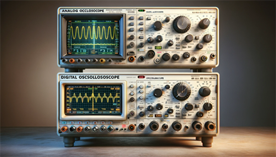
The Analog Oscilloscope represents the traditional form. It captures electrical signals directly, converting them into waveforms on the screen. With a cathode ray tube (CRT) at its core, these oscilloscopes excel in providing real-time, continuous waveform display, adept at capturing rapidly changing signals. Yet, they falter in waveform analysis, and storage capabilities, and lack digital signal processing.
Conversely, the Digital Oscilloscope employs an analog-to-digital converter (ADC). This transformation allows for enriched measurement functions and greater flexibility. Digital oscilloscopes excel beyond mere waveform display; they delve into complex signal analysis, automated measurements, signal decoding, and advanced triggering. Notably, they enable signal storage and playback for comprehensive analysis. Subcategories here range from budget-friendly, general-purpose models to advanced variants, boasting high bandwidth and sophisticated capabilities for cutting-edge electronic design and scientific research.
Figure 1: Analog Oscilloscope & Digital Oscilloscope
Classification of Uses
Diversity continues with the Ordinary Oscilloscope, a basic type used for routine signal observation and measurement. The Multifunctional Oscilloscope, equipped with extra features like automatic measurement and frequency analysis, stands out for its versatility. The Multi-line Oscilloscope can display multiple signals simultaneously, an asset in complex circuit analysis. The Multi-trace Oscilloscope, with independent channels, observes various signal waveforms. Designed for high-frequency signals, the Sampling Oscilloscope uses sampling technology to capture high-speed changes. Finally, the Storage Oscilloscope, adept at saving waveform data, is ideal for prolonged observation and analysis.
Oscilloscopes are invaluable in measuring alternating or pulsed current waveforms. Their prowess in converting electrical phenomena into visual graphics means they can observe and analyze almost any periodic physical process that can be transformed into electrical signals – think sound waves, light waves, and mechanical vibrations.
The versatility and functionality of oscilloscopes underscore their importance in ensuring the proper functioning and optimized performance of electronic systems. As technology progresses, so too do the functions and performance of oscilloscopes, evolving to meet the demands of increasingly complex electronic testing needs.
Application Scenarios of Oscilloscopes
Oscilloscopes, indispensable in designing, manufacturing, and repairing electronic equipment, are a staple for engineers. These instruments allow them to observe and analyze electrical signals, a vital step in swiftly and accurately resolving electrical measurement issues. An oscilloscope’s ability to display amplitude, frequency, peak values, and other signal information is just the beginning. More crucially, it uncovers irregularities or faults in electrical signals – noise, interference, signal distortion – information that is pivotal in evaluating and optimizing electronic devices' performance.
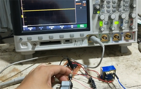
Figure 2: Circuit Design
Consider, for instance, the circuit design phase. Engineers depend on oscilloscopes to assess the performance of electronic components like transistors, capacitors, and resistors. This ensures they function correctly within the designed circuit. Moreover, during product development, oscilloscopes test the electrical performance of prototype devices. Engineers can then refine designs to meet specific performance standards.
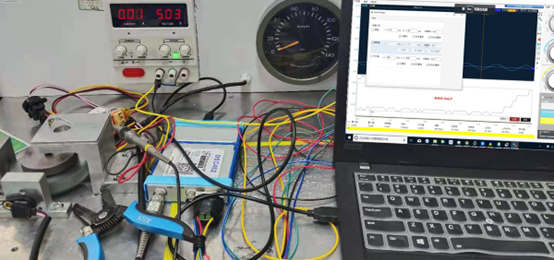
In electronic equipment repair, the role of oscilloscopes is equally vital. When a device malfunctions, engineers employ an oscilloscope to navigate through each circuit segment until they pinpoint the failure. This method significantly enhances the efficiency and accuracy of fault diagnosis.
Figure 3: Electronic Equipment Repair
Oscilloscope User Group
The oscilloscope’s versatility extends across various professional fields. It's an essential tool for scientists, engineers, physicists, service technicians, and educators. These professionals utilize oscilloscopes to analyze and interpret signals over time, applying them in diverse applications from automotive engineering to medical research.
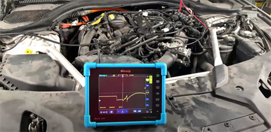
In automotive engineering, engineers analyze analog data from sensors using oscilloscopes. These data often correlate with serial data in the engine control unit (ECU). Through meticulous signal analysis, engineers gain a precise understanding of engine operation, leading to optimized vehicle performance.
Figure 4: Engineers Use Oscilloscopes to Analyze
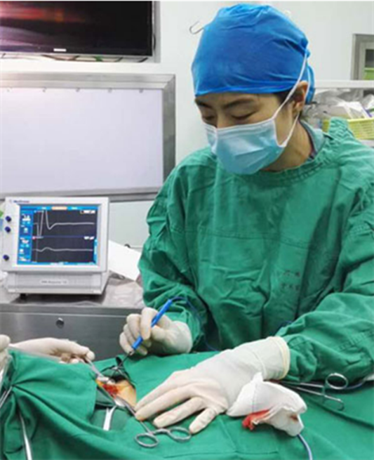
The use of oscilloscopes in medical research is equally widespread. Researchers, for example, might use them to monitor and analyze brain waves. This data is invaluable in understanding brain activity, studying neurological diseases, or developing neuroscience-related treatments. Deep analysis of brain waves aids medical experts in comprehending the brain's functions and supporting medical diagnosis and treatment.
Figure 5: Doctors Use Oscilloscopes to Analyze
In the educational sphere, oscilloscopes take a leading role. Educators employ them as teaching tools, enabling students to visually grasp the characteristics of electrical signals. By observing various waveforms, students solidify their understanding of electronic basics, laying a foundation for future scientific and engineering studies.
As a powerful instrument, the oscilloscope is pivotal not only in industry and scientific research but also in education and medical research. Its capacity to enable deep understanding and analysis of signal changes furthers the advancement of science, technology, and medicine across diverse fields.
Working Principle of Oscilloscope
An oscilloscope, a quintessential electronic test instrument, operates on the synergy of three core systems: the vertical system, the horizontal system, and the trigger system. The intricate interplay of these systems helps oscilloscopes accurately reconstruct and display electrical signals.
The Role and Optimization Mechanism of Vertical Systems
The vertical system’s main role is to regulate and optimize the voltage amplitude of the input signal. This involves scaling the input signal to suit the oscilloscope screen’s display range. A pivotal aspect of vertical amplifier design is maintaining signal authenticity, ensuring no distortion or alteration of the signal's basic characteristics during amplification. Additionally, the system offers diverse input coupling options – DC, AC, or ground – tailoring to varied test requirements.
Sampling Clock and Time Coordinates of Horizontal System
At the heart of the horizontal system lies a precise sampling clock. It provides the time coordinate for each voltage sample the oscilloscope captures. This system's responsibility is to sample the input signal at fixed, consistent intervals, crafting an accurate waveform representation. The setting of the time base, or time/divisor, dictates the waveform's horizontal expansion on the screen, essentially the displayed time span.
Condition Detection and Waveform Reconstruction of Trigger System
The trigger system's purpose is to detect specific conditions in the input signal, usually user-defined, like particular amplitudes or waveform characteristics. Upon meeting these conditions, the trigger system activates, commencing waveform data capture. This mechanism ensures the oscilloscope synchronizes and displays critical events and their surrounding waveform data accurately. A triggering system is key to ensuring a stable display of waveforms, especially when analyzing periodically changing signals or capturing infrequent events.
Oscilloscopes excel in capturing, processing, and displaying electrical signal waveforms. The vertical system guarantees an accurate signal amplitude display, the horizontal system ensures time coordinate precision, and the trigger system affords stable, reliable waveform data capture. Unitedly, these systems render the oscilloscope an indispensable tool in electronic testing and measurement. It aids engineers and technicians in deeply understanding and analyzing electronic signals, thereby playing a significant role in R&D, fault diagnosis, teaching, and other areas.
Oscilloscope Measurement Capabilities
An oscilloscope, a precision electronic measurement tool, excels in measuring voltage fluctuations, presenting this data on-screen with high detail. It transcends basic voltage and time displays, delving into multi-dimensional signal analysis, a cornerstone in electronic engineering and research.
This instrument graphically represents electrical signals, mapping voltage vertically (Y-axis) and time horizontally (X-axis). This two-dimensional portrayal enables the observation and analysis of electrical signal changes, aiding in understanding signal behavior and characteristics. Advanced oscilloscopes add another layer. They represent intensity or brightness changes on the Z-axis. This feature is important for dissecting complex signals or performing thorough troubleshooting, as it reveals subtle signal strength changes.
An oscilloscope offers far more than mere voltage and time measurements. It facilitates a deep dive into various signal aspects, including, but not limited to:
Frequency measurement of oscillating signals: Capturing periodic changes precisely, lays the groundwork for frequency analysis.
Display of circuit dynamics: Observing signal waveforms sheds light on the actual operational status of electrical signals within circuits.
Frequency analysis of specific signal segments: This aids in identifying and measuring the frequency of periodic events or atypical waveforms.
Analysis of faulty component impacts on signals: Comparing normal and abnormal waveforms helps pinpoint and locate faulty components.
Examination of the DC to AC ratio: Helps understand the composite nature of signals.
Identification of noise components and their trends: Noise analysis is key in optimizing circuit design and troubleshooting.
Overall, an oscilloscope's capabilities extend beyond simple voltage and time displays. They encompass a comprehensive analysis of an electrical signal, covering frequency, circuit dynamics, specific waveform characteristics, fault effects, and signal components. These multifaceted features render oscilloscopes indispensable in electronic engineering, fault diagnosis, scientific research, and education. They provide users with critical insights needed to deeply understand and analyze electrical signals.
How to Use Oscilloscope
Mastering the effective use of an oscilloscope helps users make electronic measurements and analyses. To harness its full potential in capturing and analyzing electrical signals, users must become adept at its operating procedures. These include navigating the front and rear panels, managing level and trigger controls, executing run commands, conducting waveform measurements, and utilizing data storage and recall functions.
Front and Rear Panel Operations
The oscilloscope's front panel, typically hosting a screen display, control knobs, and buttons, is the command center for adjusting waveform displays and measurement settings. Users must acquaint themselves with various controls - vertical and horizontal position adjustments, brightness, contrast, and more. Meanwhile, the rear panel houses vital interfaces: the power interface, data ports, and additional function interfaces like USB or Ethernet ports, enabling the oscilloscope to interface with other devices or networks.
Level and Trigger Control
Level control is about fine-tuning the vertical magnification of a signal for optimal clarity on the screen. Trigger control, on the other hand, is instrumental for stable waveform displays. Here, the user sets the trigger level to capture the signal at a specified voltage, which is especially important for analyzing periodic signals or capturing transient events.
Operation Control
Run control involves the maneuvers to start, stop, or pause waveform displays. In some scenarios, users might need to "freeze" the waveform for a closer look or employ the scroll function to examine different waveform segments.
Waveform Measurement
Oscilloscopes typically come equipped with a suite of automatic measurement functions. These allow for the measurement of various waveform parameters – frequency, amplitude, peak value, and so forth. Users can choose specific measurements and read the results directly on the screen.
Storage and Recall
Most modern digital oscilloscopes offer the functionality to store captured waveform data for later scrutiny or documentation. Additionally, users can recall previously saved waveforms for comparative analysis or further exploration.
Using an oscilloscope involves a series of steps and skills, each of which plays a decisive role in the accurate and efficient capture and analysis of electrical signals. By mastering the operation of the front and rear panels, accurately setting level and trigger parameters, deftly managing waveform controls, executing precise waveform measurements, and effectively utilizing storage and recall functions, users can maximize the oscilloscope's capabilities. This mastery helps users achieve optimal results in electronic testing and analysis.
Oscilloscope Performance Optimization
To fully harness your oscilloscope's potential and enhance its productivity, a fusion of key strategies is essential. These strategies not only pertain to the oscilloscope's operation but also its integration with external devices and customization to your specific testing requirements.
Known State Operation
Prior to initiating measurements, it’s imperative to ensure the oscilloscope is in a stable, known state. This could mean resetting the device to default or a preset configuration. Starting from this clear, predictable point significantly mitigates operational errors and confusion, thus elevating measurement accuracy and efficiency.
Minimizing Channels and Functions
Deactivating channels and features not in use on your oscilloscope can substantially lessen its processing load. This, in turn, enhances the device's responsiveness and the precision of measurements. For instance, if your task requires measuring only a single signal, switching off other input channels could decrease the oscilloscope's data processing burden, thereby augmenting its capacity for other tasks.
Streamlining Computer Connection
Linking an oscilloscope to a computer is commonly practiced for data analysis and storage. Opting for a rapid data transfer interface, such as USB 3.0, Ethernet, or even wireless, can drastically cut down on data transfer times. Additionally, employing the most current drivers and software further refines data transfer and processing speeds.
Tailoring Settings to Testing Needs
It is equally important to adjust the oscilloscope settings to suit your specific testing environment and requirements. This entails choosing suitable voltage ranges, time bases, trigger settings, and waveform display options. For example, high-frequency signal analysis calls for a higher sampling rate and bandwidth. Conversely, for monitoring low-frequency fluctuations over extended durations, a longer time base and reduced sampling rate might be necessary.
In summary, optimizing oscilloscope performance involves operating it in a known state, deactivating unneeded channels and functions, establishing efficient data connections, and customizing settings to suit test needs. Implementing these strategies not only assures measurement precision but also boosts productivity, solidifying the oscilloscope’s role as an indispensable instrument in electronic measurement and analysis.
Oscilloscope Selection Factors
Selecting the ideal oscilloscope is a critical step in ensuring successful testing outcomes. This process involves a meticulous evaluation of various technical parameters and functional features, all aimed at matching the oscilloscope to specific testing requirements. Here are key considerations:
Signal Characteristics Analysis
The initial step involves analyzing the test signal's characteristics, such as amplitude, frequency range, and whether it's a single or repeated signal. This analysis is foundational, setting the stage for determining the oscilloscope's basic performance needs.
Bandwidth Consideration
Bandwidth is indicative of the highest frequency an oscilloscope can measure effectively. As a rule of thumb, the oscilloscope's bandwidth should be at least 5 times the highest frequency of the test signal, a criterion crucial for maintaining signal integrity.
Channel Count
Assessing the number of signals to be observed concurrently is key. Multi-channel oscilloscopes offer the ability to display several signals at once, simplifying comparison and aiding comprehensive analysis.
Sampling Rate
The oscilloscope's ability to capture signal details hinges on its sampling rate. Ideally, this rate should be at least double the highest frequency of the signal, in line with Nyquist's theorem. Yet, opting for higher rates can yield a more nuanced waveform depiction.
Storage Depth
Storage depth impacts how long the oscilloscope can record waveform data. A larger memory depth is beneficial for the prolonged recording of intricate signals or for capturing fleeting events.
Display Quality
A clear, larger display with high resolution enhances the observation and analysis of signals.
Advanced Triggering Functions
Functions like pulse width triggering and video triggering are indispensable for analyzing complex signals, aiding in the capture of specific signal events.
Probe Selection
Different measurement scenarios require different types of probes. High-impedance probes are ideal for high-frequency signals, whereas differential probes are apt for measuring differences between two signals.
Additional Analysis Features
Some oscilloscopes boast extra features like spectrum analysis and serial decoding, which can be invaluable for specific applications.
User Interface and Usability
An intuitive and easy-to-use interface is crucial, particularly for complex measurement tasks, significantly boosting work efficiency.
By considering these factors, users can make an informed choice of the most appropriate oscilloscope, aligning with their specific testing needs and budget constraints. The ideal oscilloscope should offer the requisite measurement accuracy and functionality, while also being user-friendly and adaptable to potential future applications.
Oscilloscope Final Selection Guide
When finalizing the right oscilloscope for your needs, it's important to carefully weigh several key specifications. The process is similar to selecting a high-performance camera with lots of settings and interactions. Consider the following pivotal factors:
Firstly, bandwidth. This is the oscilloscope's primary performance indicator, setting the upper limit for the frequency of signals it can process without distortion. Ideally, an oscilloscope's bandwidth should outpace the highest frequency of the signal you're measuring, to avoid any signal attenuation.
Next, consider the waveform capture rate. This rate, indicating how many waveforms an oscilloscope processes each second, is essential. A robust capture rate is key for pinpointing fleeting or irregular events, particularly when analyzing dynamic or multifaceted signals.
The sampling rate is another linchpin. It dictates the oscilloscope's finesse in recording signal nuances. At a minimum, the sampling rate should be double the highest signal frequency to preserve signal integrity. Higher rates equate to more detailed waveforms.
Then, there's rise time. This measures the oscilloscope's reaction speed to signal shifts. For rapidly changing signals, an oscilloscope with a fast rise time is helpful for accurately capturing signal changes.
The trigger function is the oscilloscope's sentinel. It allows you to set specific conditions, prompting the oscilloscope to capture signals under those predefined scenarios. Varied triggering options enhance test flexibility and precision, especially in complex signal scenarios.
Finally, balance your choice with fiscal realities. High-end oscilloscopes, boasting advanced features, often carry a heftier price tag. Your decision should harmonize economic sensibility with actual needs and budget constraints.
Grasping these technical intricacies, in relation to your specific application, is the cornerstone of ensuring your oscilloscope choice aligns with your testing requirements. A thorough evaluation of these criteria, tempered with real-world application and budgetary considerations, paves the way for a judicious choice, securing the best value for your investment.


 FPGA / CPLD
 Memory
 MOS
MOS  MCU
MCU  DSP
DSP OCEP
OCEP Secondary
  Other
Other