
075582814553

A parallel plate capacitor is one of the most important types of capacitors. It is made of two flat conductive plates placed parallel to each other, with an insulating material called a dielectric between them. Parallel plate capacitors clearly show how capacitance works. Their performance depends on three main factors: the plate area, the distance between the plates, and the dielectric material used. This article explains the construction, charging circuit, working principle, formula, derivation, solved examples, and practical applications of parallel plate capacitors.
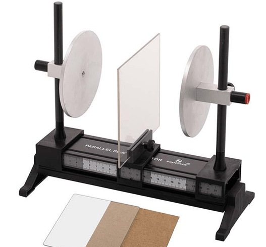
A parallel plate capacitor is built with two conductive plates placed parallel to each other. These plates are usually made from conductive metals such as aluminum, copper, or metallized foil. They are positioned close together but do not touch, leaving a small gap between them.
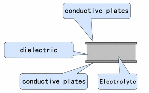
The space between the plates is filled with an insulating material called a dielectric. Common dielectric materials include air, paper, plastic film, ceramic, mica, and glass. The dielectric separates the plates, prevents direct electrical contact, and helps define the capacitor’s voltage rating and capacitance value.
External terminals or leads are connected to the two plates so the capacitor can be connected to a circuit. In practical designs, the plates and dielectric may be arranged as flat sheets, stacked layers, or rolled foil structures to save space while keeping the same basic construction.
The charging circuit of a parallel plate capacitor consists of a capacitor connected to a DC voltage source E through a switch K. The two capacitor plates, labeled A and B, are connected to opposite terminals of the battery. The voltage source provides the energy needed to move charges onto the plates, while the switch controls when the charging process begins.
When the switch K is closed, electrons flow through the external circuit from the negative terminal of the battery toward one capacitor plate. At the same time, electrons are removed from the opposite plate and pulled toward the positive terminal of the battery. As a result, plate A becomes positively charged and plate B becomes negatively charged. Since the dielectric between the plates is an insulator, charge cannot flow directly through the capacitor.
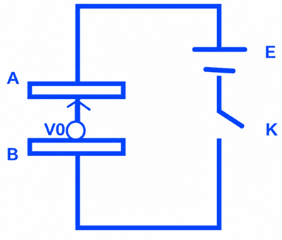
As charges accumulate on the plates, a voltage difference V₀ develops across the capacitor. This voltage gradually increases as more charge is stored. The charging current is initially at its maximum value and then decreases as the capacitor voltage approaches the battery voltage.
The charging process continues until the capacitor voltage becomes equal to the supply voltage E. At this point, the capacitor is fully charged, and current stops flowing in the DC circuit.
A parallel plate capacitor works by separating electric charge between two conductive plates. When voltage is applied, one plate becomes positively charged and the other becomes negatively charged. These opposite charges face each other across the dielectric material.
The separated charges create an electric field in the space between the plates. Since the dielectric is an insulator, it prevents the charges from moving directly from one plate to the other. Instead, the energy is stored in the electric field formed between the plates.
As the stored charge increases, the voltage across the capacitor also increases. The capacitor continues storing energy until its voltage matches the applied voltage. After that, it remains charged until it is connected to a discharge path.
The capacitance of a parallel plate capacitor depends on its physical construction. Specifically, it is determined by the area of the conductive plates, the distance between the plates, and the dielectric material placed between them. These factors determine how much electric charge the capacitor can store for a given applied voltage.
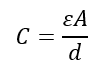
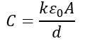
The capacitance is calculated using the formula:
Where:
C = capacitance (F)
ε = permittivity of the dielectric material (F/m)
A = effective area of one plate (m²)
d = distance between the plates (m)
This formula shows that capacitance increases when the plate area becomes larger because more charge can be stored on the plate surfaces. Capacitance also increases when a dielectric with higher permittivity is used, since the dielectric strengthens the capacitor's ability to store electrical energy. Conversely, increasing the distance between the plates reduces capacitance because the electric field becomes less concentrated.
For a capacitor with air or vacuum between the plates, the permittivity is equal to the permittivity of free space (ε₀). When another dielectric material is used, the permittivity becomes ε = εᵣε₀, where εᵣ is the relative permittivity (dielectric constant) of the material. This is why different dielectric materials can significantly affect the final capacitance value.
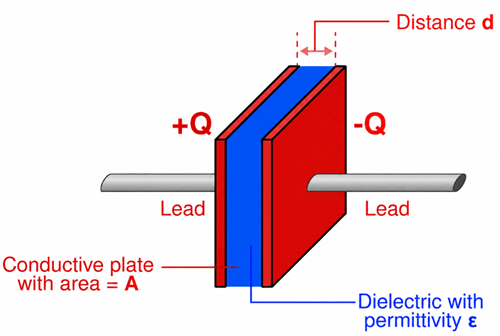
The derivation of the parallel plate capacitor formula begins with the structure shown in the figure. The capacitor consists of two large conductive plates with area A, separated by a small distance d. A dielectric material with permittivity ε fills the space between the plates. One plate carries a positive charge +Q, while the other carries an equal negative charge −Q. Because the plate separation is much smaller than the plate dimensions, the electric field between the plates can be considered uniform.
The first step is to determine the surface charge density on the plates. Surface charge density is defined as the charge distributed over the plate area:

where σ is the surface charge density, Q is the charge on the plate, and A is the plate area.
For two oppositely charged parallel plates, the electric fields produced by each plate combine in the region between them. The resulting electric field between the plates is:

Substituting the expression for surface charge density gives:

This equation shows that the electric field increases with stored charge and decreases as the plate area becomes larger.
The potential difference between the plates is equal to the electric field multiplied by the separation distance d:
V=Ed
Substituting the electric field expression:

Capacitance is defined as the ratio of stored charge to the potential difference across the capacitor:

Replacing V with the previous result gives:
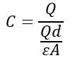
After simplification, the capacitance of a parallel plate capacitor becomes:

This final equation shows that capacitance is directly proportional to the plate area and the dielectric permittivity, while it is inversely proportional to the distance between the plates. Therefore, larger plates, a higher-permittivity dielectric, or a smaller plate separation will result in a greater capacitance value.
A parallel plate capacitor uses a dielectric with relative permittivity k = 3.5. The plate area is 0.08 m², and the distance between the plates is 0.002 m. Calculate the capacitance.
Solution:
Given:
- Area, A = 0.08 m²
- Distance, d = 0.002 m
- Relative permittivity, k = 3.5
- Permittivity of free space, ε₀ = 8.854 × 10⁻¹² F/m
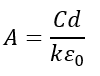
The capacitance formula is:
Substituting the values:
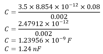
Answer: The capacitance is 1.24 nF.
A parallel plate capacitor has a capacitance of 500 pF. The plates are separated by 0.0015 m, and air is used as the dielectric (k = 1). Calculate the required plate area.
Solution:
Given:
- Capacitance, C = 500 pF = 500 × 10⁻¹² F
- Distance, d = 0.0015 m
- Relative permittivity, k = 1
- Permittivity of free space, ε₀ = 8.854 × 10⁻¹² F/m
Rearranging the capacitance formula:
Substituting the values:
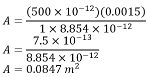
Answer: The required plate area is 0.0847 m².
• Energy Storage in Electronic Circuits - Parallel plate capacitors store electrical energy and release it when needed. They are commonly used in power supplies, timing circuits, and pulse-generation applications.
• Signal Coupling and Filtering - These capacitors help block DC signals while allowing AC signals to pass. They are widely used in amplifiers, filters, and communication circuits to improve signal quality.
• Radio Frequency and Tuning Circuits - Parallel plate capacitors are used in oscillators, resonant circuits, and radio-frequency equipment. Their capacitance helps determine operating frequencies and tuning characteristics.
• Capacitive Sensors - Changes in plate spacing or dielectric properties cause changes in capacitance. This principle is used in proximity sensors, displacement sensors, pressure sensors, and touch-sensitive devices.
• Touchscreen Technology - Capacitive touchscreens detect changes in capacitance when a finger approaches or touches the screen, enabling accurate touch input in smartphones, tablets, and control panels.
• Measurement and Testing Equipment - Parallel plate capacitors are used in laboratory instruments and testing equipment for measuring electrical properties and studying electrostatic behavior.
• Educational and Research Applications - Their simple design makes them useful for demonstrating capacitance, electric fields, dielectric materials, and charge storage in physics and engineering laboratories.

 FPGA / CPLD
 Memory
 MOS
MOS  MCU
MCU  DSP
DSP OCEP
OCEP Secondary
  Other
Other