
075582814553

CAN bus communication is widely used in automotive systems, industrial automation, robotics, medical equipment, and embedded control networks. When a CAN bus transceiver fails, the entire network may experience communication errors, missing messages, unstable data transfer, or complete bus failure. Diagnosing these problems requires a clear understanding of how the transceiver works, what commonly causes failures, and which tools are needed for accurate testing.
A CAN bus transceiver is the physical interface between the CAN controller and the CAN network. The CAN controller generates logic-level transmit and receive signals, while the transceiver converts these signals into differential signals that travel through the CANH and CANL lines.
This differential signaling method improves noise immunity because the receiver reads the voltage difference between CANH and CANL instead of relying on a single signal line. This makes CAN communication suitable for electrically noisy environments, such as vehicles, factory equipment, motor control systems, and heavy machinery.
The transceiver also protects the controller from some electrical disturbances on the bus. Many modern CAN transceivers include features such as short-circuit protection, thermal shutdown, low-power standby mode, and electrostatic discharge protection. However, these protection features do not make the device immune to wiring faults, overvoltage, poor grounding, or severe electrical stress.
CAN bus transceiver failures are often caused by problems in the physical layer of the network. This includes cables, connectors, termination resistors, power supply lines, grounding, and external electrical noise. Understanding these failure points helps technicians locate the problem faster instead of replacing parts without proper diagnosis.
Wiring damage is one of the most common causes of CAN bus communication failure. CAN cables may become cut, crushed, bent, stretched, or worn due to vibration, heat, mechanical movement, or poor installation. In vehicles and industrial systems, cables are often exposed to harsh operating conditions, making physical damage more likely over time.
A damaged wire can cause an open circuit, short circuit, or intermittent connection. If CANH or CANL is open, some nodes may stop communicating. If CANH and CANL are shorted together, the entire network may fail. If either line is shorted to ground or battery voltage, abnormal bus voltage can appear and damage the transceiver.
Connectors are also frequent failure points in CAN networks. Loose terminals, bent pins, corrosion, moisture, dust, and poor crimping can interrupt signal transmission. These problems may not always cause permanent failure. In many cases, the network works normally at first, then fails when the system vibrates, heats up, or moves.
Connector faults are difficult to diagnose because they often create intermittent communication errors. A simple visual inspection can reveal obvious damage, but some connector problems require continuity testing, voltage testing, or signal analysis with an oscilloscope.
Termination resistors help maintain signal integrity in a CAN network by reducing signal reflections along the communication bus. If the network is improperly terminated, communication reliability can decrease, especially at higher data rates or longer cable lengths. Common symptoms include distorted signals, increased communication errors, intermittent data loss, and unstable network operation.
A CAN transceiver needs a stable supply voltage to operate correctly. If the supply voltage is too low, noisy, or unstable, the transceiver may reset, stop transmitting, or produce unreliable signals. Voltage drops can happen when the power supply is overloaded, wiring resistance is too high, or grounding is poor.
Overvoltage and voltage spikes can also damage the transceiver. These problems may come from load switching, inductive devices, jump-start events, poor protection circuits, or incorrect wiring. In some cases, the transceiver may still work partially but produce abnormal voltage levels or frequent communication errors.
Electromagnetic interference (EMI) is generated by devices such as motors, relays, inverters, switching power supplies, and other high-current equipment. Excessive EMI can interfere with CAN bus signals and reduce communication reliability. In severe cases, interference may cause communication errors, corrupted messages, or temporary loss of network connectivity.
A faulty CAN bus transceiver can cause various communication problems depending on the type and severity of the failure. One common symptom is intermittent communication, where messages are sometimes transmitted successfully and sometimes lost. This can result from weak signal levels, poor connections, wiring faults, or a transceiver that becomes unstable due to heat, vibration, or electrical stress.
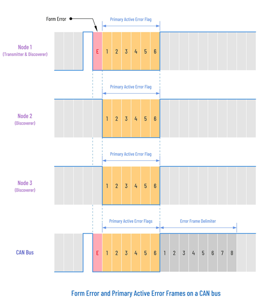
Another common symptom is an increase in CAN communication errors. As shown in figure below, when a node detects a problem such as a form error, it generates an error frame to notify other nodes on the network. Repeated error frames indicate that messages are not being transmitted or received correctly. If these errors continue to accumulate, the affected node may enter an error passive state or eventually a bus-off state, where it stops transmitting to prevent further disruption of network communication.
A faulty transceiver may also cause abnormal CANH and CANL voltage levels. The bus may become stuck in a dominant state, remain inactive, or produce voltage levels outside the expected operating range. These conditions can lead to corrupted messages, communication timeouts, and network instability. In automotive systems, such faults may trigger diagnostic trouble codes (DTCs), warning indicators, or loss of communication with electronic control units (ECUs). In industrial systems, they may cause controller alarms, machine faults, or missing sensor data.
Physical signs of failure can sometimes be observed as well. A damaged transceiver may overheat, develop burn marks, or show visible package damage. However, many transceiver failures leave no visible evidence, making electrical testing and signal analysis essential for accurate diagnosis.
Accurate CAN bus diagnosis requires the right tools. A visual inspection can find obvious problems, but electrical and communication testing are needed to confirm the actual fault. The most useful tools include a multimeter, oscilloscope, CAN bus analyzer, and diagnostic software.
A digital multimeter is used for basic electrical testing. It can measure resistance, voltage, continuity, and shorts to ground or power. One of the most important multimeter tests is measuring resistance between CANH and CANL with the system powered off. A healthy high-speed CAN network normally measures around 60 ohms.
A multimeter can also check supply voltage at the transceiver, ground quality, and abnormal voltage on the bus lines. However, a multimeter cannot show fast signal changes, noise, ringing, or waveform distortion. For deeper signal analysis, an oscilloscope is needed.
An oscilloscope is one of the most effective tools for evaluating CAN signal quality. It displays the actual CANH and CANL waveforms and helps identify noise, signal reflections, voltage spikes, ringing, and other signal integrity problems that may affect network communication.
A CAN bus analyzer monitors and decodes communication traffic on the network. It can display CAN identifiers, data frames, error frames, bus load, message timing, and communication activity between nodes. This makes it useful for finding missing messages, repeated errors, incorrect baud rates, or faulty nodes.
Unlike a basic multimeter, a CAN analyzer helps identify communication-level problems. It is especially useful when the physical wiring looks normal but the network still has errors. Some analyzers also support CAN FD, logging, filtering, and protocol decoding.
Diagnostic software is commonly used in automotive and industrial systems to read fault codes, monitor live data, and check communication status. It can show whether a module is online, offline, or reporting CAN-related errors. Some software can also display error counters, bus-off conditions, and communication logs.
The usefulness of diagnostic software depends on system compatibility. Automotive tools may read diagnostic trouble codes from ECUs, while industrial tools may monitor controller communication and fieldbus activity. Diagnostic software is most effective when used together with electrical testing and waveform analysis.
A systematic diagnostic process helps avoid guesswork. CAN bus problems should be checked from the simplest physical issues first before moving to advanced signal and communication analysis. This prevents unnecessary replacement of transceivers, controllers, or modules.
Inspect cables, connectors, and transceiver packages for physical damage, corrosion, loose connections, overheating, or contamination. Many CAN network faults originate from simple mechanical problems that can be identified through careful visual examination.
Use a multimeter to verify termination resistance, supply voltage, and CAN bus voltage levels. A properly terminated high-speed CAN network typically measures about 60 Ω between CANH and CANL when powered off. Voltage measurements can also help identify short circuits, open circuits, grounding issues, and power supply problems that may affect transceiver operation.
Use an oscilloscope to examine CANH and CANL waveforms. Signal analysis helps identify waveform distortion, noise, signal reflections, voltage spikes, and other issues that may affect communication quality.
Use a CAN bus analyzer or diagnostic software to monitor network traffic, review error frames, analyze communication activity, and identify nodes that may be generating faults.
If a transceiver is suspected to be faulty, compare its behavior with a known working device or test it within a verified network. This helps confirm whether the fault originates from the transceiver or another part of the system.
• Supply Voltage - Choose a CAN bus transceiver that matches the system voltage. Many high-speed CAN networks use 5 V, while some embedded systems use 3.3 V. Using the wrong voltage rating can cause unstable communication or device damage.
• Data Rate - Check the maximum supported communication speed. Standard high-speed CAN commonly supports up to 1 Mbps, while CAN FD transceivers support faster data-phase speeds. Use a CAN FD transceiver if the network uses CAN FD.
• CAN FD Support - CAN FD is required when the system needs faster data transfer and larger message payloads. Replacing a CAN FD transceiver with a standard CAN transceiver can cause communication errors.
• Operating Temperature Range - Select a transceiver that can handle the actual working environment. Automotive and industrial systems often need wider temperature ratings because they may face heat, cold, vibration, and long operating hours.
• ESD and Surge Protection - Good protection helps the transceiver survive electrostatic discharge, voltage spikes, and harsh electrical conditions. This is important in automotive, industrial, and outdoor applications.
• Short-Circuit Protection - This protects the device if CANH or CANL is accidentally shorted to ground, supply voltage, or each other. It helps reduce the risk of permanent damage.
• Pin Compatibility - Always compare the datasheets before replacing a CAN transceiver. Similar parts may have different standby, silent mode, enable, or power pins. Wrong pin connections can damage the circuit.
• Low-Power or Standby Mode - This is useful for battery-powered systems or vehicles that need low current consumption when communication is inactive.
Before replacing a CAN bus transceiver, verify that the replacement device matches the original design requirements. Important factors include supply voltage, supported data rate, CAN FD compatibility, operating temperature range, protection features, and pin configuration. If the underlying cause of failure is not corrected, the replacement transceiver may also fail.
Preventive maintenance helps reduce CAN bus failures and keeps communication stable over time. Recommended practices include:
• Regularly inspect cables for cuts, abrasion, crushing, excessive bending, or heat damage.
• Check connectors for loose terminals, bent pins, corrosion, moisture, dust, or poor crimp connections.
• Inspect grounding points to ensure clean, secure, and low-resistance connections.
• Correct small physical issues early to prevent intermittent communication errors or complete network failure.
• Use twisted-pair CAN cable to improve noise immunity and signal integrity.
• Route CAN cables away from high-current power lines, motors, relays, inverters, and switching power supplies.
• Use shielded CAN cable in environments with high electromagnetic interference (EMI).
• Install termination resistors only at the two ends of the CAN bus and verify proper termination during maintenance.
• Maintain a stable power supply and protect transceivers from voltage surges, voltage drops, and excessive ripple.
• Ensure proper grounding to reduce common-mode noise and unwanted voltage differences between nodes.
• Use surge protection, ESD protection, and industrial-grade components in harsh operating environments.
• Periodically measure resistance between CANH and CANL to verify network integrity.
• Check CAN bus voltage levels to detect shorts, opens, or power-related issues.
• Use an oscilloscope to inspect CANH and CANL waveforms for noise, ringing, reflections, or signal distortion.
• Monitor CAN traffic with a CAN analyzer or diagnostic software to identify developing communication problems before network failure occurs.
CAN bus transceiver failures should not be diagnosed by replacing parts immediately. Many problems come from wiring damage, poor connectors, incorrect termination, unstable power, or EMI. A step-by-step process using visual inspection, electrical testing, waveform analysis, and CAN monitoring helps find the real fault faster. With proper installation, correct component selection, and routine maintenance, CAN networks can stay reliable and reduce unexpected downtime.

 FPGA / CPLD
 Memory
 MOS
MOS  MCU
MCU  DSP
DSP OCEP
OCEP Secondary
  Other
Other