
075582814553

RF systems often need to separate useful signals from unwanted noise, harmonics, and nearby channels. This is where a Chebyshev RF filter becomes important. It is designed to give a sharper cutoff than many basic filter types, which means it can reject unwanted frequencies more quickly after the cutoff point. In this article, you will learn what a Chebyshev RF filter is, how it works, its main types, key specifications, and more.
A Chebyshev RF filter is a type of radio frequency (RF) filter designed to provide a sharper transition between the passband and stopband than a Butterworth filter of the same order. It achieves this improved selectivity by allowing controlled ripple in either the passband or stopband, depending on the filter design. By attenuating signals outside the desired frequency range, these filters help improve signal quality and reduce interference. It is a popular choice in RF circuits where bandwidth control, signal isolation, and spectrum efficiency are important design requirements.
The image below shows the frequency response of a Chebyshev filter compared with a Butterworth filter. A Chebyshev RF filter works by allowing signals within a desired frequency range to pass while attenuating unwanted frequencies outside that range. Its main characteristic is the presence of controlled ripple in the passband, which helps achieve a much steeper roll-off near the cutoff frequency.
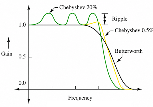
In the graph, the green curve (Chebyshev 20%) has larger passband ripple. Because more ripple is allowed, the filter transitions very quickly from the passband to the stopband. This provides excellent frequency selectivity but causes greater variation in signal gain within the passband.
The yellow curve (Chebyshev 0.5%) has much smaller ripple. It still offers a sharper cutoff than a Butterworth filter while maintaining a more stable passband response.
The black curve (Butterworth) has a completely flat passband with no ripple. However, its roll-off is more gradual, meaning unwanted frequencies are not attenuated as quickly near the cutoff frequency.
In RF systems, the input signal contains both desired and undesired frequency components. The Chebyshev filter passes the desired frequencies with minimal loss and rapidly attenuates frequencies beyond the cutoff point.
Chebyshev RF filters are mainly classified into Type I Chebyshev filters and Type II Chebyshev filters. Both types are designed to provide sharper frequency selectivity than many basic filter designs, but they place ripple in different parts of the frequency response.
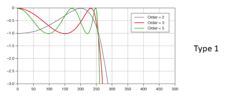
• Type I Chebyshev Filter – A Type I Chebyshev filter has ripple in the passband. This means the gain slightly rises and falls before the cutoff frequency. As shown in the Type I response image, higher filter orders create more ripple cycles and a sharper drop after the cutoff point. This type is commonly used when strong frequency separation is needed, such as in RF receivers, transmitters, and communication systems.
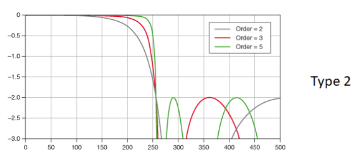
• Type II Chebyshev Filter – A Type II Chebyshev filter, also called an inverse Chebyshev filter, has a flatter passband but ripple in the stopband. As shown in the Type II response image, the desired signal range stays more stable before the cutoff frequency, while the rejected frequency range contains ripple. This type is useful when passband signal accuracy is more important, but the circuit still needs strong rejection of unwanted frequencies.
The main difference of these types is where the ripple appears. Type I places ripple in the passband to achieve a faster transition after the cutoff frequency. Type II keeps the passband flatter and places ripple in the stopband. In practical RF design, Type I is often chosen for sharper selectivity, while Type II is better when a cleaner passband response is required.
Several key specifications determine the performance of a Chebyshev RF filter. These specifications affect how sharply the filter separates desired and unwanted frequencies, how much signal variation is allowed, and how much signal loss occurs in the RF path.
Passband ripple is one of the defining characteristics of a Chebyshev filter. Unlike a Butterworth filter, which has a flat passband, a Chebyshev filter allows controlled gain variation within the passband. Ripple is usually specified in decibels, such as 0.1 dB, 0.5 dB, or 1 dB. A higher ripple value usually gives a steeper roll-off, but it also creates more amplitude variation in the wanted signal.
The cutoff frequency marks the transition between the passband and stopband. It is the point where the filter begins to attenuate signals more strongly. In RF systems, the cutoff frequency determines which frequency range is allowed to pass and which range is rejected.
Filter order refers to the number of reactive elements or filter stages used in the design. A higher-order Chebyshev filter provides sharper frequency separation and stronger attenuation of unwanted signals. However, it also requires more components, increases circuit complexity, and may increase insertion loss.
Roll-off rate describes how quickly the filter reduces signals beyond the cutoff frequency. Chebyshev filters are known for their steep roll-off, which makes them useful when unwanted frequencies are close to the desired signal. This is one reason they are commonly used in RF receivers, transmitters, and communication circuits.
Stopband attenuation shows how much the filter reduces unwanted signals outside the passband. It is measured in decibels. Higher stopband attenuation means better suppression of interference, harmonics, and adjacent-channel signals.
Insertion loss is the amount of signal power lost as the signal passes through the filter. In RF circuits, lower insertion loss is preferred because it helps preserve signal strength and improves system efficiency.
Frequency selectivity refers to how well the filter separates desired frequencies from unwanted frequencies. A Chebyshev filter has high selectivity because its ripple-based design allows a sharper transition between the passband and stopband.
Chebyshev RF filters are usually designed for a specific source and load impedance, commonly 50 Ω or 75 Ω in RF systems. Proper impedance matching helps reduce signal reflections, return loss, and unwanted standing waves.
The image shows a typical Type I Chebyshev filter response. The small ripple in the passband and the steep attenuation after the cutoff frequency are key characteristics of Chebyshev filters.
The magnitude response is given by:
|H(jω)| = 1 / √[1 + ε²Tn²(ω/ωc)]
Where:
• |H(jω)| = magnitude response
• ε = ripple factor
• Tn = nth-order Chebyshev polynomial
• ω = angular frequency
• ωc = cutoff angular frequency
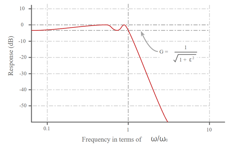
The minimum passband gain is:
Gmin = 1 / √(1 + ε²)
The ripple factor can be calculated from the passband ripple specification:
ε = √(10^(Rp/10) − 1)
Where Rp is the passband ripple in decibels (dB).
These equations are commonly used when designing Chebyshev filters and calculating their frequency response. They help determine the relationship between ripple, filter order, cutoff frequency, and attenuation characteristics.
The following examples show common second-order Chebyshev filter circuits based on the Sallen-Key topology.
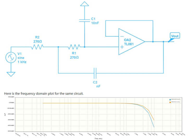
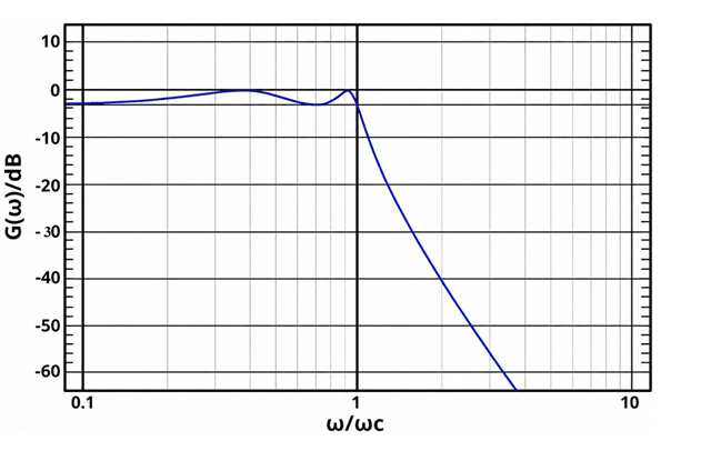
This circuit is a second-order Type I Chebyshev low-pass filter implemented using a TL081 operational amplifier. The resistor-capacitor network determines the cutoff frequency and ripple characteristics, while the op-amp provides buffering and stability. Signals below the cutoff frequency pass with minimal attenuation, while higher-frequency components are rapidly attenuated. The frequency-response plot shows the characteristic passband ripple and steep roll-off of a Chebyshev filter.
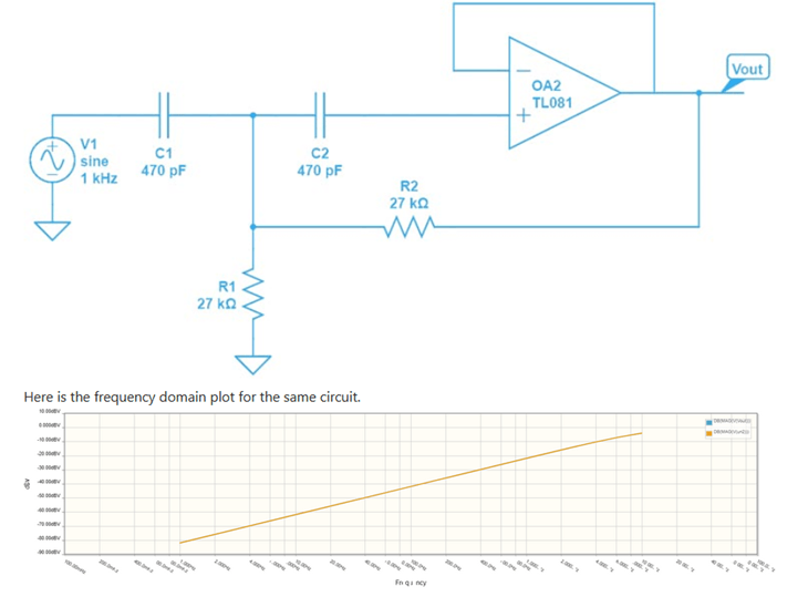
The second-order Type I Chebyshev high-pass filter based on the Sallen-Key configuration. The capacitors at the input block low-frequency signals while allowing higher-frequency signals to pass. The resistor-capacitor network and op-amp determine the cutoff frequency and filter response. The accompanying frequency-response plot shows increasing gain above the cutoff frequency while attenuating lower-frequency components.
• Wireless communication systems - Chebyshev RF filters are used to separate desired frequency bands and reduce interference from nearby channels.
• RF receivers - Helps remove unwanted signals, noise, and adjacent-channel interference before signal processing.
• RF transmitters - Suppresses harmonics and unwanted frequency components before the signal is transmitted.
• Radar systems - Chebyshev RF filters provide sharp frequency control for reliable signal detection and target measurement.
• Satellite communication equipment - Helps maintain clean signal transmission and reception over crowded frequency bands.
• RF test instruments - Used in spectrum analyzers, signal generators, and communication testers to improve measurement accuracy.
| Parameter | Chebyshev Filter | Butterworth Filter | Bessel Filter | Elliptic Filter |
| Passband Ripple | 0.01–3 dB | 0 dB | 0 dB | 0.01–3 dB |
| Stopband Ripple | 0 dB (Type I) | 0 dB | 0 dB | 0.01–3 dB |
| Normalized Passband Gain | ±Rp dB | 0 dB | 0 dB | ±Rp dB |
| Roll-Off Rate per Pole | 20 dB/decade | 20 dB/decade | 20 dB/decade | 20 dB/decade |
| Selectivity Factor (Relative) | 0.8–0.9 | 0.5–0.7 | 0.3–0.5 | 0.9–1.0 |
| Group Delay Variation | Medium | Low | Lowest | Highest |
| Phase Linearity | Medium | Good | Excellent | Poor |
| Overshoot in Step Response | 5–30% | 4–15% | <5% | 20–40% |
| Attenuation at 2× Cutoff (5th Order Example) | ~50–55 dB | ~30–35 dB | ~20–25 dB | ~60–70 dB |
| Attenuation at 1.5× Cutoff (5th Order Example) | ~30–35 dB | ~18–22 dB | ~10–15 dB | ~40–50 dB |
| Filter Order Required for 40 dB Rejection* | 4–5 | 6–8 | 8–10 | 3–4 |
| Typical Insertion Loss (RF) | 0.5–3 dB | 0.3–2 dB | 0.3–2 dB | 1–4 dB |
| Typical Return Loss | 15–25 dB | 20–30 dB | 20–30 dB | 15–25 dB |
| Typical VSWR | 1.2:1–1.5:1 | 1.1:1–1.5:1 | 1.1:1–1.5:1 | 1.3:1–1.8:1 |
| Component Sensitivity | Medium | Low | Low | High |
| Design Complexity | Medium | Low | Low | High |
A Chebyshev RF filter’s main advantage is its steep roll-off characteristic, which allows it to attenuate nearby unwanted frequencies more quickly than a Butterworth or Bessel filter of the same order. When choosing a Chebyshev RF filter, consider the required cutoff frequency, passband ripple, stopband attenuation, insertion loss, and system impedance. Applications that need maximum frequency selectivity often benefit from a higher ripple value and higher filter order, while applications requiring more stable signal amplitude may use lower ripple values.

 FPGA / CPLD
 Memory
 MOS
MOS  MCU
MCU  DSP
DSP OCEP
OCEP Secondary
  Other
Other