
075582814553

Input impedance and output impedance are two important parameters that affect how an operational amplifier (op-amp) interacts with other parts of a circuit. Although op-amps are often selected based on gain, bandwidth, or power consumption, impedance plays a major role in determining signal accuracy, voltage transfer, and overall circuit performance. This article explains the basic of input impedance and output impedance, their effects on amplifier performance, and practical guidelines for choosing an op-amp based on impedance requirements.
Input impedance is the resistance or opposition that an operational amplifier presents to the signal connected to its input terminal. In simple terms, it shows how much the op-amp “loads” the signal source. A high input impedance means the op-amp draws very little current from the input signal, while a low input impedance can pull more current and affect the original signal.
In an ideal op-amp, the input impedance is assumed to be infinite. This means no current enters the input terminals, and the op-amp can read the input voltage without changing it. However, real op-amps are not perfect. They still draw a very small input current, so their input impedance is high but not infinite.
In practical op-amps, input impedance depends on the input stage technology. Bipolar-input op-amps typically have input impedance ranging from 100 kΩ to 10 MΩ. JFET-input op-amps usually offer much higher values, often between 10¹¹ Ω and 10¹³ Ω. CMOS-input op-amps can provide even higher input impedance and often exceed 10¹² Ω. These high impedance values help minimize loading effects and improve signal accuracy in sensor and measurement applications.

In the diagram, the input impedance is represented by Zin, connected from the input line to ground. This is a simplified way to show that the op-amp input is not completely open. Even though the input current is usually very small, the source still “sees” an impedance at the op-amp input.
High input impedance is important because it helps preserve signal accuracy. For example, sensors, voltage dividers, and weak signal sources may not be able to supply much current. If the op-amp input impedance is too low, it can reduce the signal voltage before amplification. This is called loading effect, and it can cause measurement errors or signal loss.
Input impedance is not always purely resistive. At higher frequencies, the input capacitance of the op-amp also becomes important. This capacitance can add extra loading to AC signals, slow down fast signal changes, and cause distortion if the circuit is not designed properly.
Output impedance is the internal opposition that an operational amplifier presents at its output terminal. In a simple model, it can be represented as a small resistance placed in series with the op-amp output. This resistance is usually called Rout.
In an ideal op-amp, the output impedance is zero. This means the amplifier can deliver the exact output voltage to any load without voltage loss. However, real op-amps are not ideal. Their output stage has limits, so a small voltage drop can occur when the connected load draws current.
The output impedance of a practical op-amp varies by design and operating conditions. While the internal open-loop output impedance may be relatively high, negative feedback significantly reduces the effective closed-loop output impedance. In many modern op-amps, the closed-loop output impedance is often less than 1 Ω, allowing efficient voltage transfer and stable operation when driving external loads.

The image above shows this idea by placing Rout between the op-amp output and the final output terminal. When the load current is low, the voltage drop across Rout is very small. The output signal remains close to the intended value. However, when the load draws more current, the voltage drop across Rout becomes larger. As a result, the voltage received by the load may be lower than the voltage produced inside the op-amp.
Low output impedance helps the op-amp drive external circuits more effectively. It keeps the output voltage stable, reduces signal loss, and improves the amplifier’s ability to work with different load conditions. This is especially useful when the op-amp is connected to low-resistance loads, cables, filters, ADC inputs, or other circuit stages.
Output impedance also affects signal accuracy and performance at higher frequencies. In practical circuits, the output resistance can interact with load capacitance and cause slower response, ringing, or reduced bandwidth. For this reason, you can check both the op-amp’s output current limit and its ability to drive capacitive or low-impedance loads.
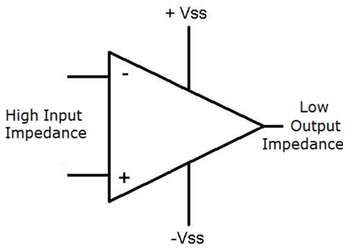
High input impedance prevents the op-amp from disturbing the source signal, while low output impedance allows it to deliver a clean and stable output signal to the next stage.
The image below shows two amplifier stages connected in cascade. The output impedance (Zout) of the first amplifier is connected to the input impedance (Zin) of the second amplifier. Although each amplifier may work properly on its own, the interaction between these impedances can affect signal strength and frequency response when multiple stages are connected together.

The output impedance of the first amplifier and the input impedance of the second amplifier create a voltage divider. Because of this, the second amplifier may receive a lower voltage than the original output voltage produced by the first stage. The greater the difference between Zin and Zout, the more efficiently the signal is transferred.
The input voltage seen by an amplifier can be estimated using the voltage divider equation:

Where:
• Vin = Voltage reaching the amplifier input
• Vsource = Source signal voltage
• Zin = Amplifier input impedance
• Rs = Source impedance
A higher input impedance allows more of the source voltage to reach the amplifier input, reducing signal loss.
The output voltage delivered to a load is also affected by output impedance. The amplifier output and load form another voltage divider.

Where:
• VLoad = Voltage across the load
• Vout = Amplifier output voltage before loading
• RLoad = Load resistance
• Zout = Amplifier output impedance
A lower output impedance allows more voltage to be delivered to the load and improves driving capability.
The image also shows the input capacitance (Cin) of the second amplifier. Together with the output impedance (Zout) of the first amplifier, it forms an RC low-pass filter. As frequency increases, this combination can attenuate high-frequency components, reducing bandwidth and slowing signal transitions.
As a result, excessive output impedance or input capacitance can lead to:
• Reduced signal amplitude
• Lower overall gain
• Limited bandwidth
• High-frequency attenuation
• Slower response time
• Choose high input impedance for weak signal sources. Sensors, voltage dividers, and measurement circuits often produce small signals and cannot supply much current. A high input impedance minimizes loading and helps preserve signal accuracy.
• Select low output impedance for driving loads. Low output impedance allows the op-amp to deliver voltage to the load with minimal signal loss and better voltage stability.
• Match the op-amp to the source impedance. As a general rule, the op-amp input impedance should be much higher than the source impedance. This ensures that most of the source voltage reaches the amplifier input.
• Consider the load requirements. If the op-amp must drive low-resistance loads, long cables, or multiple circuit stages, choose a device with sufficient output current capability and low output impedance.
• Evaluate high-frequency performance. In high-speed circuits, output impedance and input capacitance can affect bandwidth and signal quality. Select an op-amp designed for the required operating frequency.
• Use buffer amplifiers when necessary. A voltage follower or buffer stage can provide very high input impedance and very low output impedance, improving signal transfer between circuit stages.
• Check the datasheet specifications. Review input impedance, output impedance, input bias current, output current, and bandwidth to ensure the op-amp meets the application's requirements.
Input and output impedance are not just small datasheet details. They directly affect signal quality, voltage transfer, and circuit reliability. In most designs, choose an op-amp with input impedance much higher than the source impedance and output impedance much lower than the load impedance. This helps reduce signal loss and keeps the amplifier working accurately.

 FPGA / CPLD
 Memory
 MOS
MOS  MCU
MCU  DSP
DSP OCEP
OCEP Secondary
  Other
Other