
075582814553

With integrated memory, digital I/O pins, analog features, and communication interfaces, the PIC18F452 can handle many control and data-processing tasks within a single chip. This article will discuss the PIC18F452 microcontroller, including its pinout, specifications, features, programming method, alternatives, and comparison with other microcontrollers.
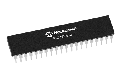
The PIC18F452 is a high-performance 8-bit microcontroller developed by Microchip Technology. It belongs to the PIC18 family and is designed with a RISC architecture that provides efficient instruction execution and reliable performance. The device integrates a CPU, memory, and multiple peripherals on a single chip, allowing it to control electronic systems and process data in embedded designs.
This microcontroller features 32 KB of Flash program memory, 1536 bytes of RAM, and 256 bytes of EEPROM for data storage. It can operate at clock speeds of up to 40 MHz, providing fast processing capability for control tasks. The PIC18F452 also includes 34 digital I/O pins, making it flexible for interfacing with external components.
In addition, the device provides built-in peripherals such as timers, a 10-bit ADC with multiple channels, and serial communication modules including USART, SPI, and I²C. These integrated features help simplify circuit design while maintaining reliable system operation.
If you are interested in purchasing the PIC18F452, feel free to contact us for pricing and availability.
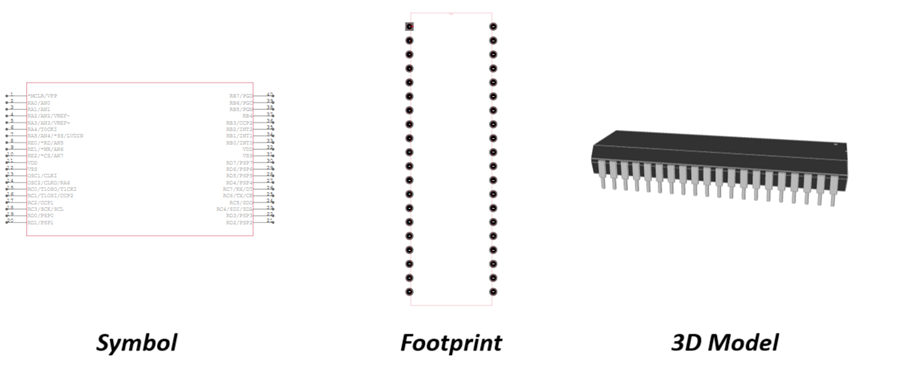
PIC18F452-I/P symbol, footprint and 3d model.
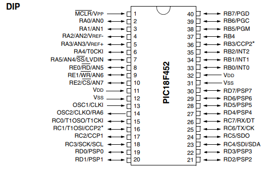
| Pin No. | Pin Name | Type | Description |
| 1 | MCLR/VPP | Input | Master Clear (Reset) / Programming voltage |
| 2 | RA0/AN0 | I/O | Analog input channel 0 / Port A bit 0 |
| 3 | RA1/AN1 | I/O | Analog input channel 1 / Port A bit 1 |
| 4 | RA2/AN2/VREF- | I/O | Analog input channel 2 / Negative voltage reference |
| 5 | RA3/AN3/VREF+ | I/O | Analog input channel 3 / Positive voltage reference |
| 6 | RA4/T0CKI | I/O | Timer0 external clock input |
| 7 | RA5/AN4/SS/LVDIN | I/O | Analog input channel 4 / SPI Slave Select / Low-voltage detect |
| 8 | RE0/RD/AN5 | I/O | Parallel Slave Port Read / Analog input 5 |
| 9 | RE1/WR/AN6 | I/O | Parallel Slave Port Write / Analog input 6 |
| 10 | RE2/CS/AN7 | I/O | Parallel Slave Port Chip Select / Analog input 7 |
| 11 | VDD | Power | Positive supply voltage |
| 12 | VSS | Power | Ground |
| 13 | OSC1/CLKI | Input | Oscillator input / External clock input |
| 14 | OSC2/CLKO/RA6 | I/O | Oscillator output / Clock output |
| 15 | RC0/T1OSO/T1CKI | I/O | Timer1 oscillator output / Timer1 clock input |
| 16 | RC1/T1OSI/CCP2 | I/O | Timer1 oscillator input / CCP2 module |
| 17 | RC2/CCP1 | I/O | Capture/Compare/PWM module 1 |
| 18 | RC3/SCK/SCL | I/O | SPI clock / I²C clock |
| 19 | RD0/PSP0 | I/O | Parallel Slave Port data bit 0 |
| 20 | RD1/PSP1 | I/O | Parallel Slave Port data bit 1 |
| 21 | RD2/PSP2 | I/O | Parallel Slave Port data bit 2 |
| 22 | RD3/PSP3 | I/O | Parallel Slave Port data bit 3 |
| 23 | RC4/SDI/SDA | I/O | SPI data input / I²C data |
| 24 | RC5/SDO | I/O | SPI data output |
| 25 | RC6/TX/CK | I/O | USART transmit / synchronous clock |
| 26 | RC7/RX/DT | I/O | USART receive / data |
| 27 | RD4/PSP4 | I/O | Parallel Slave Port data bit 4 |
| 28 | RD5/PSP5 | I/O | Parallel Slave Port data bit 5 |
| 29 | RD6/PSP6 | I/O | Parallel Slave Port data bit 6 |
| 30 | RD7/PSP7 | I/O | Parallel Slave Port data bit 7 |
| 31 | VSS | Power | Ground |
| 32 | VDD | Power | Positive supply voltage |
| 33 | RB0/INT0 | I/O | External interrupt 0 |
| 34 | RB1/INT1 | I/O | External interrupt 1 |
| 35 | RB2/INT2 | I/O | External interrupt 2 |
| 36 | RB3/CCP2 | I/O | Capture/Compare/PWM module 2 |
| 37 | RB4 | I/O | Port B digital I/O |
| 38 | RB5/PGM | I/O | Low-voltage programming input |
| 39 | RB6/PGC | I/O | Programming clock |
| 40 | RB7/PGD | I/O | Programming data |
• PIC18F4520
• PIC18F4620
• PIC18F4550
• PIC18F458
• PIC18F4580
• PIC18F2520
• PIC18F2550
• PIC18F2420
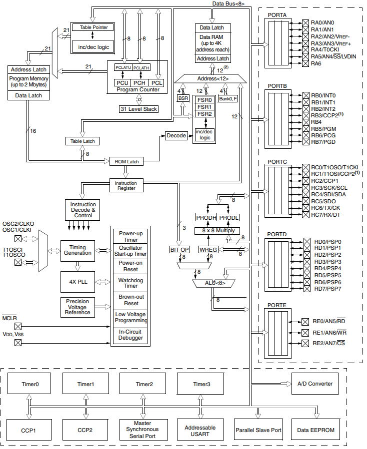
| Specification | Details |
| CPU Type | 8-bit PIC18 RISC architecture |
| Clock Speed | DC – 40 MHz |
| Performance | Up to 10 MIPS |
| Total Instructions | 75 Instructions |
| Flash Memory | 32 KB |
| Instructions | 16,384 instructions |
| SRAM | 1536 Bytes |
| EEPROM | 256 Bytes |
| Interrupt Sources | 18 Interrupt sources |
| Digital I/O | Ports A, B, C, D, E |
| Available Pins | Up to 34 programmable I/O pins |
| Timer Modules | 4 timers (1×8-bit, 3×16-bit) |
| CCP Modules | 2 CCP modules |
| ADC Resolution | 10-bit Analog-to-Digital Converter |
| ADC Channels | 8 input channels |
| Communication Modules | MSSP, Addressable USART |
| Supported Interfaces | SPI, I²C, USART |
| Parallel Interface | PSP (Parallel Slave Port) |
| Reset Types | POR, BOR, RESET Instruction, Stack Full, Stack Underflow |
| Reset Delays | PWRT, OST |
| Brown-out Reset | Programmable Brown-out Reset |
| Low Voltage Detect | Programmable Low Voltage Detect |
| Supply Voltage | 2.0 V – 5.5 V |
| Power Saving Mode | Sleep mode |
| Safety Feature | Watchdog Timer (WDT) |
| Clock Sources | External crystal, RC oscillator |
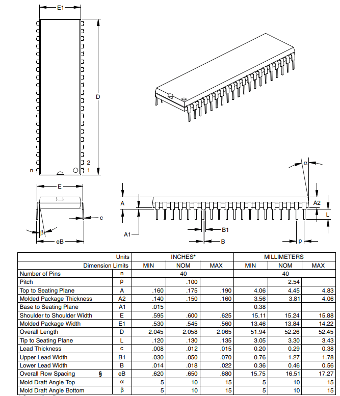
| Available Packages | 40-pin DIP, 44-pin PLCC, 44-pin TQFP |
| Temperature Range | −40°C to +85°C (industrial) |
The PIC18F452 uses a high-performance RISC CPU architecture optimized for C compilers. It supports PIC16 and PIC17 instruction sets and provides efficient processing with up to 10 MIPS performance at a maximum 40 MHz clock frequency. The device uses 16-bit wide instructions and an 8-bit data path, allowing fast and efficient execution of control tasks.
The microcontroller integrates 32 KB Flash program memory, 1536 bytes of RAM, and 256 bytes of data EEPROM. It supports linear program memory addressing up to 32 KB and data memory addressing up to 1.5 KB, making it suitable for complex firmware storage and data handling.
The PIC18F452 includes several built-in timer modules. Timer0 can operate as an 8-bit or 16-bit timer/counter, while Timer1 and Timer3 are 16-bit timers used for precise timing operations. Timer2 is an 8-bit timer with a programmable period register, often used for PWM timing control.
The device provides two Capture/Compare/PWM (CCP) modules that support capture, compare, and PWM operations. The capture mode offers 16-bit resolution, while the compare mode provides 100 ns timing resolution. PWM mode supports 1- to 10-bit resolution, enabling precise signal control.
The PIC18F452 includes multiple communication modules for data exchange. The Master Synchronous Serial Port (MSSP) supports SPI and I²C communication, while the addressable USART module supports RS-485 and RS-232 communication protocols.
This microcontroller integrates a 10-bit Analog-to-Digital Converter (ADC) with 8 input channels and fast sampling capability. It also supports conversion during sleep mode and maintains linearity of ≤1 LSB. Additional features include Programmable Low Voltage Detection (PLVD) and Programmable Brown-Out Reset (BOR) for reliable operation.
The PIC18F452 supports self-programmable Flash memory, allowing firmware updates through software. It also includes Power-on Reset (POR), Power-up Timer (PWRT), Oscillator Start-up Timer (OST), and Watchdog Timer (WDT) for system stability and protection.
The device supports multiple oscillator modes including primary oscillator with Phase-Locked Loop (PLL) and a secondary 32 kHz oscillator. These options allow designers to select suitable clock sources depending on performance and power requirements.
Built using CMOS technology, the PIC18F452 offers low power consumption and a wide operating voltage range of 2.0 V to 5.5 V. It also supports Sleep mode for energy savings and maintains long data retention of more than 40 years for Flash and EEPROM memory.
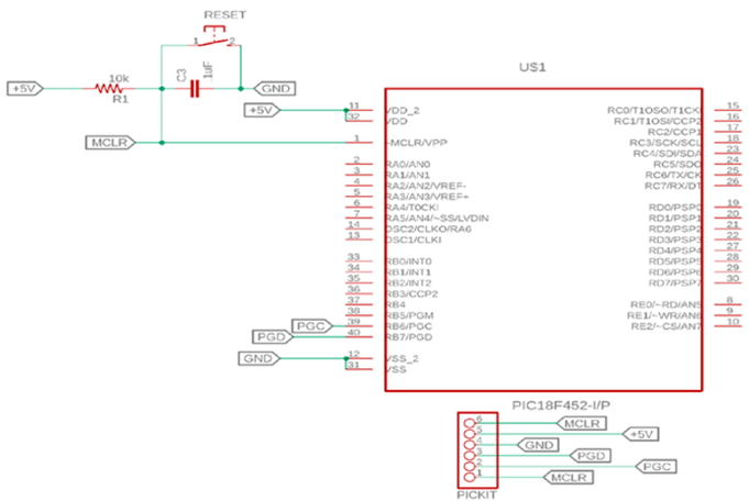
The PIC18F452 can be programmed using In-Circuit Serial Programming (ICSP), which allows firmware to be uploaded to the microcontroller while it is installed on the circuit board. A programmer such as a PICkit is commonly used together with MPLAB X IDE to write and upload the program into the device’s Flash memory.
In the diagram, the MCLR/VPP pin is connected to +5V through a 10 kΩ resistor, with a 0.1 µF capacitor to ground for reset stability. The VDD pins connect to +5V and VSS pins connect to ground to power the microcontroller.
Programming is done through the ICSP pins: RB6 (PGC) for the programming clock and RB7 (PGD) for programming data. These pins connect to the PICkit programmer, which sends the firmware to the PIC18F452. After programming, the microcontroller resets and begins running the uploaded code.
• Industrial automation systems
• Motor control systems
• Robotics control units
• Embedded control systems
• Data acquisition systems
• Sensor interface systems
• Home automation devices
• Communication interface devices
• Measurement and monitoring equipment
• Consumer electronics controllers
| Feature | PIC18F452 | PIC18F4520 | PIC16F877A | ATmega328P |
| Manufacturer | Microchip | Microchip | Microchip | Microchip (formerly Atmel) |
| CPU Architecture | 8-bit PIC18 | 8-bit PIC18 | 8-bit PIC16 | 8-bit AVR |
| Maximum Clock Speed | 40 MHz | 40 MHz | 20 MHz | 20 MHz |
| Program Memory | 32 KB Flash | 32 KB Flash | 14 KB Flash | 32 KB Flash |
| RAM | 1536 Bytes | 1536 Bytes | 368 Bytes | 2 KB |
| EEPROM | 256 Bytes | 256 Bytes | 256 Bytes | 1 KB |
| I/O Pins | Up to 34 | Up to 36 | Up to 33 | Up to 23 |
| ADC | 10-bit, 8 channels | 10-bit, 13 channels | 10-bit, 8 channels | 10-bit, 6 channels |
| Timers | 4 | 4 | 3 | 3 |
| Communication | USART, SPI, I²C | USART, SPI, I²C | USART, SPI, I²C | USART, SPI, I²C |
| Operating Voltage | 2.0 – 5.5 V | 2.0 – 5.5 V | 4.0 – 5.5 V | 1.8 – 5.5 V |
| Package Options | DIP, PLCC, TQFP | DIP, TQFP | DIP, PLCC | DIP, TQFP |
Microchip Technology Inc. is a global semiconductor company known for designing and manufacturing microcontrollers, analog devices, and embedded control solutions. The company operates advanced wafer fabrication, assembly, and testing facilities that produce high-reliability semiconductor components used in industrial, automotive, consumer electronics, aerospace, and communication systems. Its manufacturing capabilities focus on high quality, long product lifecycles, and strong supply chain support.

 Catalogue
 FPGA / CPLD
 Memory
 MOS
MOS  MCU
MCU  DSP
DSP OCEP
OCEP Secondary
  Other
Other 


