
075582814553

USB technology enables reliable communication between computers and a wide range of devices. From simple peripherals like keyboards and mice to high-performance storage and display systems, USB provides a standardized way to handle data transfer, power delivery, and device control. This article will discuss the USB software structure, hardware architecture, evolution of USB standards, connector types, and how to choose the right USB type for your needs.
The USB software structure is built around a host-controlled system that manages communication between the computer and connected devices. Instead of working as independent units, USB devices rely on a layered software architecture where each level has a specific role. This design allows stable data transfer, efficient power control, and smooth interaction between hardware and applications.
At the foundation of the USB system is the bus interface layer, which connects the physical hardware with higher-level software operations. This layer is responsible for linking the electrical signaling of the USB connection with the communication protocols used by the system.
A key component here is the USB host controller, which manages all data movement between the host (computer) and connected USB devices. It ensures that data flows correctly while handling important system resources such as bandwidth allocation and power distribution. These functions are essential for modern USB standards, especially when multiple devices are connected at the same time.
Within this layer, several software components work together:
• Host Controller Driver (HCD) - This driver acts as the bridge between the operating system and the USB controller hardware. It translates system-level requests into commands that the hardware can execute.
• USB Core Interface (System USB Stack) - Instead of being a single driver, this layer manages communication rules, device enumeration, and overall USB operations. It ensures that devices are correctly identified and configured when connected.
• Driver Interface (USBD Concept) - This provides a standard way for device drivers to communicate with the USB system. Data is transferred using structured requests, often organized through logical channels called pipes.
The host software layer is responsible for managing how the operating system interacts with USB devices. In modern systems such as Windows, macOS, and Linux, this functionality is already built into the OS.
This layer handles tasks such as:
• Device detection and initialization
• Configuration and resource assignment
• Communication between system drivers and hardware
In older or legacy systems, additional software was sometimes required to support USB functionality. Today, however, the process is fully integrated, allowing devices to work automatically when plugged in.
At the top of the structure is the USB client software layer, which includes device drivers and user-level applications. This is where the USB system becomes useful to the end user.
When a USB device is connected, the system loads the appropriate driver. This driver communicates with the USB stack and allows applications to interact with the device. For example:
• A keyboard driver sends input data to the system
• A storage driver manages file transfers
• An application accesses the device through standard system interfaces
This layer ensures that user actions are translated into meaningful operations on the connected hardware.
USB hardware architecture is designed to provide a simple, scalable, and reliable connection system between a host device and multiple peripherals. It follows a structured layout where a single host controller manages communication across connected devices through hubs and cables.
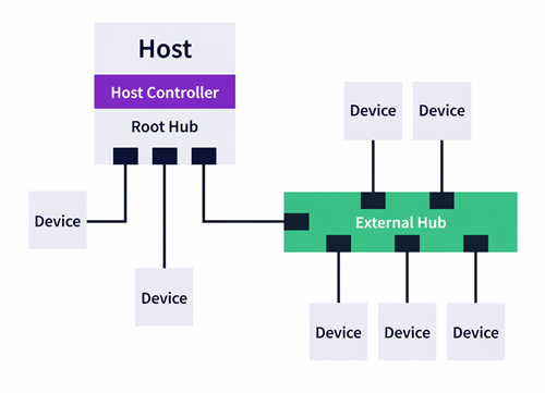
At its core, USB uses a cascaded star topology. This means all devices connect outward from a central host, either directly or through hubs. The host controller acts as the main control point, managing communication with up to 127 connected devices in a single USB system.
Modern USB standards, including USB 3.x and USB4, improve this architecture by using multiple differential signal pairs for high-speed data transfer. In addition, dedicated lines such as Configuration Channel (CC) pins are used for power negotiation and role detection. These improvements allow USB to support advanced features like Power Delivery (PD), which can provide up to 240W of power for demanding devices.
Unlike older communication systems, USB operates as a token-based bus. The host sends requests (tokens), and only the addressed device responds. This controlled communication method reduces data collisions and ensures consistent performance across all connected devices.
The USB hardware structure is built around three main elements: the host, hubs, and functions. Each plays a specific role in maintaining system operation.
The host, also known as the root, is the central controller of the USB system. It is typically integrated into the motherboard or available as an expansion card. The host includes the USB controller and a root hub, which serves as the starting point for all USB connections.
Its main role is to:
• Control data flow between devices
• Manage device addressing and communication timing
• Allocate bandwidth and system resources
Every USB system has one host, and all communication is initiated from this point.
A hub expands the number of available USB ports, allowing multiple devices to connect to a single host. It acts as a distribution point, forwarding data between the host and connected peripherals.
Hubs are responsible for:
• Detecting when devices are connected or removed
• Managing power distribution to each port
• Supporting error handling and connection stability
They can be:
• Bus-powered (drawing power from the host)
• Self-powered (using an external power source)
This flexibility makes hubs essential for building larger USB networks.
A function refers to any end device connected to the USB system, such as a mouse, keyboard, external storage, or camera. These devices perform specific tasks and respond to commands sent by the host.
Each function:
• Has a unique address assigned by the host
• Communicates only when requested
• Operates based on its defined device class or driver
This structured communication ensures smooth interaction between hardware and software layers.
USB hardware architecture is built on a host-controlled, scalable framework that connects multiple devices through a clear and organized structure. By combining a cascaded star topology with intelligent components like hosts, hubs, and functions, USB systems deliver reliable data transfer, efficient power management, and flexible device connectivity.
USB technology has evolved significantly since its introduction, transforming from a simple data interface into a high-speed, multi-purpose connection standard. Over the years, improvements in speed, power delivery, and functionality have allowed USB to support everything from basic peripherals to high-performance devices. Understanding this progression helps users choose the right standard for modern applications.
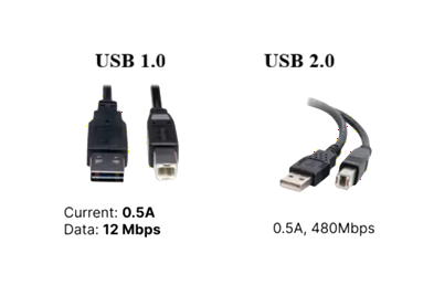
The first version of USB, USB 1.0, was introduced in 1996 with a maximum speed of 1.5 Mbps. It marked the beginning of a universal connection method but had limited performance.
By 1998, USB 1.1 improved reliability and increased speed to 12 Mbps (Full Speed), making it more practical for everyday use.
The major breakthrough came with USB 2.0, released in 2000. It introduced High-Speed transfer rates of up to 480 Mbps, which significantly improved data performance. Even today, USB 2.0 remains widely used for devices like keyboards, mice, and audio interfaces due to its low cost, compatibility, and stable performance.
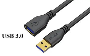
The introduction of USB 3.0 marked a major shift toward high-speed data transfer with the launch of SuperSpeed USB. Over time, naming conventions changed, but the performance improvements remained consistent.
Modern USB 3.x classifications include:
• USB 3.2 Gen 1 (formerly USB 3.0) - Supports speeds up to 5 Gbps, suitable for general data transfer and external storage.
• USB 3.2 Gen 2 (formerly USB 3.1) - Increases bandwidth to 10 Gbps, enabling faster file transfers and improved device performance.
• USB 3.2 Gen 2x2 - Uses dual-lane operation to reach 20 Gbps, typically requiring a USB Type-C connection.
These advancements allow USB to handle larger data loads efficiently, especially for modern storage devices and high-resolution media workflows.
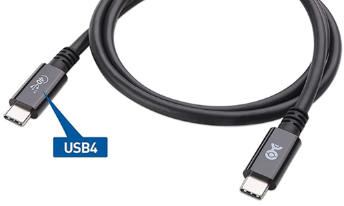
The release of USB4 introduced a more advanced architecture based on the Thunderbolt 3 protocol, enabling dynamic bandwidth sharing across multiple data types. This allows a single cable to carry data, video, and power simultaneously.
As of today, USB4 Version 2.0 represents the latest stage in USB evolution, offering significant performance improvements.
• Maximum Speed - Up to 80 Gbps (bidirectional), with the ability to reach 120 Gbps (asymmetric) for high-resolution display applications such as 8K.
• Protocol Tunneling - Supports multiple protocols, including USB 3.2, DisplayPort 2.1, and PCIe, through a single connection.
• USB Type-C Standardization - Exclusively uses the USB Type-C connector, ensuring compatibility with modern devices.
These features make USB4 ideal for high-performance computing, professional video workflows, and advanced peripheral connectivity.
To simplify understanding, modern USB naming often reflects performance rather than technical specification:
| Specification | USB 5Gbps | USB 10Gbps | USB 20Gbps | USB 40Gbps | USB 80Gbps |
| Technical Spec | USB 3.2 Gen 1 | USB 3.2 Gen 2 | USB 3.2 Gen 2x2 | USB4 (Gen 3x2) | USB4 Version 2.0 |
| Maximum Speed | 5 Gbps | 10 Gbps | 20 Gbps | 40 Gbps | 80 Gbps |
| Connector Type | Type-A / Type-C | Type-A / Type-C | Type-C only | Type-C only | Type-C only |
| Lanes Used | 1 lane | 1 lane | 2 lanes | 2 lanes | 2 lanes (bi-directional) |
| Power Delivery | Optional | Supported | Supported | Required | EPR up to 240W |
| Video Support | Limited | Yes (Alt Mode) | Yes | Yes (DisplayPort/Thunderbolt) | Advanced (multi-display, 8K+) |
| Backward Compatibility | Yes | Yes | Yes | Yes | Yes |
| Typical Use Case | Basic devices, flash drives | External SSDs, docks | High-speed storage | 4K/8K displays, pro docks | Advanced workstations, high-end systems |
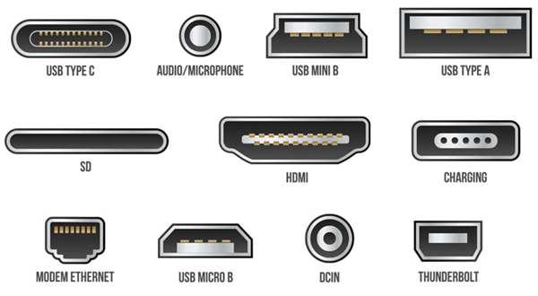
USB connectors have evolved alongside USB standards, moving from larger, single-purpose ports to a compact, high-performance universal interface. While modern devices now rely heavily on USB Type-C, older connector types are still found in legacy systems, industrial equipment, and older consumer electronics. Understanding these connector types helps ensure proper compatibility and efficient device usage.
The USB Type-A connector is the most recognizable USB interface. It is commonly used as the host-side connector on computers, chargers, and hubs. This rectangular connector has been widely adopted across multiple USB generations, from USB 1.0 to USB 3.x.
Despite the rise of Type-C, Type-A remains relevant due to:
• Wide compatibility with existing devices
• Strong physical durability
• Continued use in desktops, industrial systems, and accessories
However, it lacks modern features such as reversibility and advanced power delivery.
The Mini-B connector was once widely used in early portable electronics. It was commonly found in:
• MP3 players
• Older digital cameras
• Portable storage devices
This connector offered improved durability compared to earlier designs and helped standardize device connectivity at the time. However, its larger size and limited performance led to its replacement by smaller and more efficient connectors. Today, Mini-B is considered obsolete in most consumer applications but may still appear in older equipment.
The Micro-USB connector became the global standard for smartphones and portable devices before the introduction of USB Type-C. It supports USB 2.0 speeds up to 480 Mbps and was widely used for both data transfer and charging.
Key characteristics include:
• Compact size compared to Mini-B
• Broad adoption across mobile devices
• Basic charging and data capabilities
However, Micro-USB has several limitations:
• Non-reversible design (can only be inserted one way)
• Lower power delivery capability
• More fragile physical structure over time
These limitations led to its gradual replacement by USB Type-C.
The USB Type-C connector represents the current standard for modern devices. It is designed as a universal interface that supports high-speed data, video output, and high-power charging through a single cable.
Type-C is now widely adopted and supported by global regulations, including the EU Common Charger Directive, making it the default interface for many devices.
• Reversible Design - The symmetrical shape allows insertion in either direction, improving usability.
• High Power Delivery (USB PD) - Supports Extended Power Range (EPR) up to 240W (48V/5A), enabling charging for laptops and high-power devices.
• Alternate Modes (Alt Modes) - Can carry multiple signal types, including DisplayPort, HDMI, and Thunderbolt, alongside standard USB data.
• High-Speed Performance - Works with advanced standards like USB 3.x and USB4 for significantly higher data transfer rates.
Selecting the correct USB type depends on your device, performance requirements, and intended use. For basic peripherals like keyboards or mice, USB 2.0 or USB Type-A is still sufficient. However, for modern applications such as external SSDs, high-resolution displays, or fast charging, USB Type-C with USB 3.x or USB4 support is the better choice.
You should consider factors such as data transfer speed, power delivery capability, and device compatibility. Choosing the right USB type ensures optimal performance and prevents limitations in speed or charging efficiency.

 FPGA / CPLD
 Memory
 MOS
MOS  MCU
MCU  DSP
DSP OCEP
OCEP Secondary
  Other
Other